
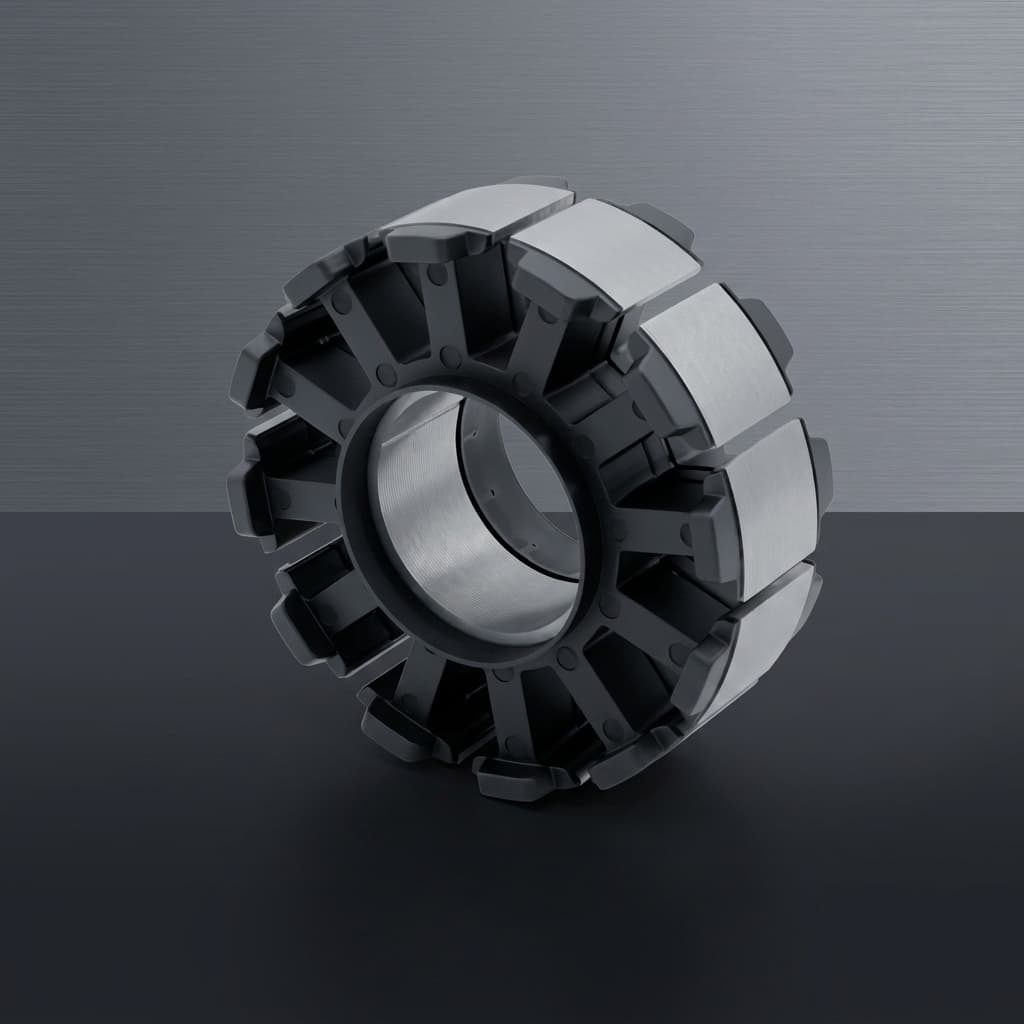
SMC Stator Prototyping: A DFM Guide for Axial Flux Motor Engineers
A precise Design for Manufacturability (DFM) guide for motor design teams transitioning axial flux stator prototypes into Soft Magnetic Composite (SMC) mass production.
Executive Summary
- The Core Problem: Transitioning from 3D CAD to a physical SMC stator prototype often fails due to unrealistic aspect ratios, sharp internal corners, and ignoring powder flow dynamics during compaction.
- DFM First: Design for Manufacturability (DFM) must occur before magnetic simulation is locked in. You cannot press what you cannot eject.
- The Solution: Following specific SMC design rules—such as drafting angles (0.5°-1°), generous radii (>0.5mm), and avoiding thin walls—ensures high density (>7.3 g/cm³) and structural integrity.
- Machining Limits: Limit post-compaction CNC machining on SMC to 0.3mm - 0.5mm on air gap faces to prevent particle smearing, which degrades the inter-particle insulation and increases surface eddy currents.
The transition from a laminated steel prototype to a mass-produced Soft Magnetic Composite (SMC) axial flux stator is the most critical phase in a motor program. Often, a stator geometry that was easily wire-EDM cut from electrical steel during the R&D phase is fundamentally impossible to manufacture using high-tonnage powder metallurgy compaction.
Prototyping an Axial Flux Permanent Magnet (AFPM) motor is exhilarating; transitioning that prototype into high-volume, reliable mass production is where the real engineering begins. If you are leveraging Soft Magnetic Composites (SMC) for your stator core, you are already ahead of the curve regarding magnetic performance at high frequencies. However, SMC powder metallurgy carries unique Design for Manufacturability (DFM) rules that differ entirely from traditional electrical steel laminations.
In this guide, we break down the critical DFM considerations for SMC stator prototyping, complete with factory-level specifications and tolerance targets to ensure your core geometry can be compacted efficiently and cost-effectively.
1. The Powder Compaction Paradigm
Unlike electrical steel, which is stamped from a 2D sheet, SMC parts are created by compressing insulated iron powder inside a precision tool (die) under extreme pressure (typically 600 to 800 MPa).
This fundamental shift means you must design your stator teeth with compaction direction (Z-axis) in mind.
Avoid Undercuts and Overhangs
The compacted part must be ejected vertically from the die. Any geometric feature that prevents the top or bottom punches from retracting, or traps the part inside the die cavity, is an undercut.
- The Rule: If you cannot "see" a feature from a top-down orthogonal view along the compaction axis, it cannot be pressed directly.
- The Factory Fix: Redesign the tooth profile to eliminate the undercut, or plan for secondary CNC machining operations (SMC machines similarly to cast iron, easily accommodating threaded holes or side grooves post-compaction).
2. Aspect Ratios and Density Gradients
SMC powder does not flow like liquid plastic in an injection mold; it is pushed. Because of inter-particle friction and friction against the die walls, the pressure distribution during compaction is not perfectly uniform.
Managing Height-to-Width Ratios
If a stator tooth is extremely tall and narrow, the powder at the center of the part will experience less pressure than the powder directly contacting the punches. This creates a "density gradient," where the center of the part is less dense (e.g., dropping from 7.4 g/cm³ to 7.0 g/cm³), leading to weaker mechanical strength and lower magnetic permeability.
- The Rule: Keep the length-to-wall-thickness ratio below 3:1 to 5:1 whenever possible.
- The Factory Fix: For exceptionally thick stators (e.g., >30mm axial length), consider pressing two thinner halves (each 15mm) and bonding them together during assembly. This ensures uniform density throughout the magnetic flux path.
3. Draft Angles and Radii: Saving Your Tooling
SMC relies heavily on the structural integrity of the compaction tooling. Sharp internal corners in your part geometry require sharp external corners on the tooling punches. Under 800 MPa of pressing force, sharp tooling corners act as severe stress concentrators and are highly prone to chipping or catastrophic failure.
Radii Guidelines
- The Rule: Eliminate sharp corners. Apply a minimum radius of R0.5 mm to R1.0 mm on all internal and external edges aligned with the pressing direction.
- Why it matters: This not only dramatically increases tooling life (from 5,000 shots to over 100,000 shots) but also improves powder flow into narrow sections during the die-filling stage, preventing "soft spots" in the final part.
Draft Angles
While perfectly vertical walls are possible in SMC, adding a slight draft angle greatly assists in the ejection process, reducing friction and die wear.
- The Rule: Provide a draft angle of 0.5° to 1.0° on deep vertical faces if it does not negatively impact the magnetic air gap or winding slot.
4. Segmented vs. Monolithic Stators
One of the most frequent questions we receive from OEMs during DFM review is whether to press a complete, monolithic stator ring or segment it into individual teeth.
| Feature | Monolithic Ring | Segmented Teeth (YASA) |
|---|---|---|
| Tooling Tonnage | Extremely High (>1,000 tons) | Low to Medium (100 - 500 tons) |
| Winding Process | Complex needle winding | Simple, high-speed bobbin winding |
| Copper Fill Factor | Moderate (40-50%) | Exceptional (60-75%) |
| Assembly Complexity | Low (single piece) | High (requires fixture/carrier) |
Our Recommendation: For motors exceeding 100mm in diameter, segmented stator teeth are almost always the superior choice for high-volume manufacturing. The drastic improvement in copper fill factor (thanks to bobbin winding) often outweighs the added complexity of assembling the segments into an aluminum or composite carrier.
5. Post-Machining Allowances and Tolerances
SMC parts are "near-net-shape," meaning they emerge from the die very close to their final dimensions. A well-designed tool can achieve dimensional tolerances of IT7 to IT8 (roughly ±0.03 mm to ±0.08 mm depending on the dimension).
However, for critical mating surfaces—such as the air-gap facing surface which directly impacts motor efficiency—tighter tolerances may be required to achieve a minimal air gap (e.g., 0.5 mm gap).
- The Factory Fix: Leave a machining allowance of 0.3 mm to 0.5 mm on the air gap faces. After curing, these faces can be ground or milled.
- Warning: Heavy or aggressive machining can smear the iron particles on the surface, potentially shorting the microscopic insulation layer and locally increasing surface eddy currents. Always use sharp tools and minimal feed rates when cutting SMC.
Tooling Readiness
Transitioning from a laminated prototype to an SMC mass-production stator requires a shift in engineering mindset. By eliminating undercuts, managing aspect ratios, applying generous radii, and leveraging segmented architectures, you can drastically reduce tooling costs and accelerate your time to market.
Frequently Asked Questions
Q: What is the maximum diameter for a monolithic SMC stator? A: For monolithic rings, we generally cap the Outer Diameter (OD) around 150mm. Beyond this, the required pressing tonnage exceeds standard hydraulic limits, making segmented teeth (YASA topologies) the financially viable alternative for mass production.
Q: Can you thread a hole directly into an SMC part? A: No. Because SMC is a compacted powder, cutting threads directly into the material will result in stripping under high torque. We recommend designing for through-holes or pressing in threaded metal inserts post-compaction for secure mounting.
Send your STEP files to our engineering team for a rapid tooling feasibility analysis and tonnage calculation.
Article-to-RFQ Workflow
Turn this guide into an evidence-ready RFQ.
Use the article context as the starting point, then align CAD status, magnetic targets, validation scope, and release records before asking suppliers to quote.
Capture the decision
Identify the topology, product family, operating point, and current gate before the article takeaway becomes a supplier question.
Attach buyer inputs
Prepare drawing status, magnetic targets, quantity plan, destination, and open risks in the RFQ worksheet.
Request evidence
Ask for DFM notes, first article inspection, magnetic validation, traceability, and packaging release files before price comparison.
Author

Categories
More Posts
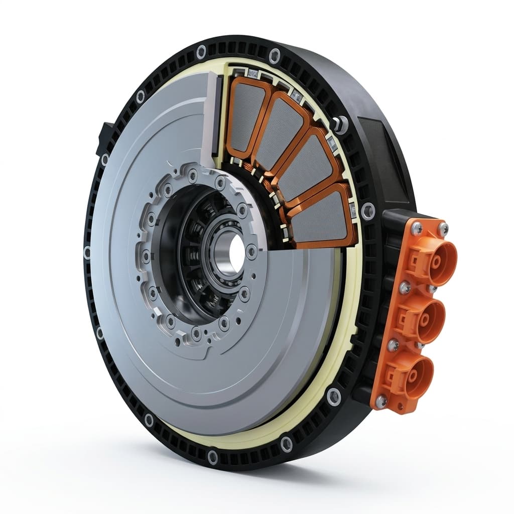
Mercedes-Benz Launches Large-Scale Axial Flux Motor Production: What It Means for the Supply Chain
Mercedes-Benz axial flux motor production in Berlin changes AFPM sourcing. See supplier tolerances, SMC stator risks, evidence gaps, and RFQ actions.
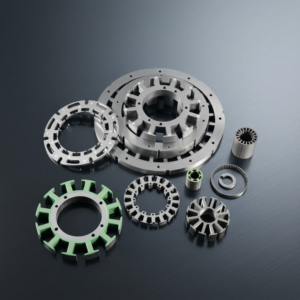
Thermal Management in Axial Flux Motors: Direct Oil Cooling and Stator Core Design
Engineering guide to axial flux motor thermal management, direct oil cooling, SMC stator design, validation risks, supplier evidence, and RFQ checks for buyers.
Axial Flux Motor Topologies (YASA, AFIR, TORUS): A Core Sourcing & Procurement Guide
Compare YASA, AFIR, and TORUS axial flux motor topologies for stator core sourcing, SMC vs laminated steel choices, RFQ risk control, and DFM review.