WhatsApp
Axial Flux Core LogoAxial Flux Core
  • Home
  • Contact Us
Start inquiry
Axial Flux Core LogoAxial Flux Core

SMC axial flux motor core and AFPM stator OEM support for advanced electric drive teams.

Inquiry Email

[email protected]

Email app

Attach STEP/DXF/PDF plus frequency, flux density, sample quantity, annual forecast, and destination.

Instant Chat

+8618857971991

Chat on WhatsApp

Direct response from our engineering team.

Core Products
  • Product Portfolio
  • Axial Flux Motor Core
  • AFPM SMC Stator
  • SMC Stator Segments
  • YASA Segmented Stator Teeth
  • 3D Isotropic Flux Core
  • Lamination & Winding Services
  • Custom Compaction Tooling
Applications
  • Applications Overview
  • eVTOL Axial Flux Cores
  • Humanoid Joint Stators
  • Drone Propulsion Cores
  • EV Supercar AFPM Cores
  • Compact Generator Cores
Manufacturing & Quality
  • OEM Capability Hub
  • Technology & Materials
  • SMC Core Manufacturing
  • Manufacturing & Quality
  • Axial Flux Stator Prototyping
  • Compaction Tooling DFM
  • Magnetic Loss Validation
  • AFPM Manufacturing Route Tool
  • AFPM Core Design Checklist
  • AFPM Air Gap Design Tool
  • AFPM Cooling Design Tool
  • AFPM Cogging Torque Tool
Resources
  • Blog
  • About
  • Contact / RFQ
  • Engineering Resources
  • Privacy Policy
  • Cookie Policy
  • Terms of Service
© 2026 Axial Flux Core. All Rights Reserved.|Backed by Linkup Ai Co., Ltd. with axial flux core manufacturing support in Shenzhen and Dongguan, China.
Legal entity: Linkup Ai Co., Ltd.
← Back to Products

Lamination & Winding Services

Axial lamination and winding support for AFPM stators with dynamic punching, polygon correction, flat-wire coils, varnish insulation, Hi-pot, and RFQ scope.

Target Buyer:For motor R&D, sourcing, and manufacturing teams comparing SMC with thin silicon steel, or needing an axial lamination core, wound stator, insulation process, and electrical release package under one RFQ.
Request Custom QuoteDownload RFQ Templates
Axial lamination stator core reference for low-frequency AFPM winding route review

Capability Highlights

  • Low-frequency silicon-steel route review for axial flux stators where high permeability and torque density outweigh SMC geometry benefits
  • Dynamic punching, synchronized winding, tape-wound stack, laser-cut, wire-EDM, and fixture route comparison by drawing
  • Polygon correction planning for OD, ID, pitch drift, slot position, air-gap face, and datum control before sample release
  • Flat-wire, hairpin, I-pin, bobbin, and concentrated winding feasibility review with slot-fill and cooling boundary inputs
  • Integrated insulation scope covering self-bonding, laser spot welds, varnish impregnation, epoxy coating, resistance, surge, and Hi-pot checks

Typical Applications

  • Low-speed high-torque AFPM stators
  • Axial lamination motor prototypes
  • Turnkey wound stator assemblies
  • Silicon-steel baseline builds for SMC-versus-lamination comparison
  • Flat-wire concentrated winding trials for compact disc motors

Engineering Focus

  • Route decision: when low-frequency, high-permeability silicon steel is more practical than SMC, and where SMC remains the better 3D flux route
  • Lamination process route: dynamic punching, synchronized winding, tape-wound core, wire-EDM, laser cutting, burr control, and interlaminar insulation
  • Polygon correction: OD/ID roundness, slot pitch drift, air-gap face, datum scheme, fixture strategy, and inspection method
  • Stack locking: self-bonding coating, adhesive, clamp fixture, laser spot weld, thermal distortion risk, and eddy-current short path review
  • Winding interface: flat-wire, hairpin, I-pin, bobbin, concentrated coil, slot opening, turn count, coil insertion, clearance, and thermal path
  • Electrical release: resin varnish impregnation, epoxy coating, insulation class, resistance, surge, Hi-pot, sample ID, and acceptance report format

Engineering Datasheet

Lamination and winding services should be scoped as a controlled process package. The buyer should separate lamination manufacturing, stack locking, winding, insulation, impregnation, coating, inspection, electrical testing, and final acceptance before comparing quotes.

ParameterRFQ Planning RangeEngineering Note
Lamination material route0.10-0.35 mm silicon steel planning discussion for low-frequency AFPM programsFinal material grade and thickness depend on frequency, permeability, loss target, cutting route, coating, burr control, and supplier availability.
Process routeDynamic punching, synchronized winding, tape-wound stack, wire-EDM, laser cut, or hybrid sample routeThe route should be chosen from magnetic target, volume, slot geometry, polygon control, burr limit, and tooling budget.
Axial stator envelopeOD 30-800 mm; ID 25 mm min.; axial height 5-110 mmEnvelope feasibility should be checked against strip route, winding access, fixture strategy, stack locking, and final inspection reach.
Slot count planning range3-112 slotsSlot opening, tooth pitch, polygon effect, pitch drift, coil insertion, and lead exit drive manufacturability.
Polygon correctionOD/ID roundness, slot pitch, circular runout, and air-gap face correction by fixture and inspection planA plus/minus 0.5 mm class planning target can be discussed only when process route, part size, and measurement method are locked.
Edge and insulation controlBurr limit, deburring, coating integrity, interlaminar resistance, and short-path reviewCut edges, welds, burrs, and handling damage can create interlaminar shorts that defeat the purpose of laminations.
Stack locking methodSelf-bonding coating, adhesive, clamp fixture, laser spot weld, or mechanical retention by drawingThe locking method should be reviewed for heat distortion, eddy-current bridges, datum shift, and later winding access.
Winding routeConcentrated winding, flat wire, hairpin, I-pin, bobbin, or post-assembly winding reviewThe winding method should be frozen before lamination geometry, slot opening, lead exit, and insulation clearances are released.
Impregnation and coatingResin varnish impregnation, vacuum-assisted varnish, epoxy powder coating, masking, and cure route by drawingCoating and impregnation should be quoted separately from bare lamination and bare winding scope.
Electrical acceptanceResistance, phase balance, surge, insulation resistance, Hi-pot, visual lead check, and sample ID recordElectrical acceptance criteria should be quoted separately from dimensional core acceptance.
Release evidenceFAI, CMM/3D scan, slot pitch report, burr note, stacking factor, coating note, electrical test report, and packing recordA wound stator sample should ship with records that separate core geometry, stack quality, winding, insulation, and final electrical tests.

Process Notes

  • Confirm whether the design benefits from silicon-steel laminations at the operating frequency before choosing this route over SMC.
  • Translate the electromagnetic model into manufacturable CTQs: slot opening, tooth pitch, OD/ID roundness, air-gap face, stack height, lead exit, and winding clearance.
  • Review dynamic punching, synchronized winding, tape-wound stack, laser cut, wire-EDM, polygon correction, and fixture strategy before prototype route selection.
  • Separate bare core, stack locking, winding, coating, impregnation, lead termination, and final electrical validation so quote scope is not ambiguous.
  • Treat welds, adhesive, self-bonding, varnish, and epoxy coating as engineering variables because they can change distortion, insulation, heat flow, and rework risk.

Validation Notes

  • Recommended buyer inputs: lamination stack drawing, winding diagram, wire specification, target frequency, flux density, thermal target, insulation class, and Hi-pot requirement.
  • Recommended dimensional records: FAI, CMM/3D scan, OD/ID, slot pitch, air-gap face, stack height, burr or edge-quality notes, and stacking factor.
  • Recommended process records: strip material or lamination lot, coating type, bonding or weld method, impregnation route, cure condition, masking map, and sample IDs.
  • Recommended electrical records: resistance, phase balance, insulation resistance, surge scope, Hi-pot result, lead check, and final acceptance language when included.

Evidence Pack

Audit-Ready Proof Package

For custom product RFQs, the useful proof is a controlled evidence package: drawings, material route, inspection records, validation scope, and sample acceptance notes.

Download templatesQuality controlsRequest evidence scope

Can the buyer justify why a lamination route is preferred over SMC for this axial flux stator?

Evidence to Prepare

Operating frequency, target flux density, loss model, permeability requirement, torque profile, SMC comparison notes, and cost or volume target.

Acceptance Focus

Prevents choosing laminations only by habit when SMC may better support 3D flux, high frequency, or near-net-shape geometry.

Can polygon correction be verified with a defined datum and measurement method?

Evidence to Prepare

OD/ID tolerance, slot pitch target, air-gap face CTQ, fixture concept, CMM or 3D scan method, and acceptance report format.

Acceptance Focus

Turns polygon effect from a vague process risk into an inspectable tolerance plan before sample approval.

Can edge quality and stack locking avoid interlaminar shorts?

Evidence to Prepare

Burr limit, deburr route, coating integrity check, self-bonding or weld map, interlaminar resistance scope, and visual criteria.

Acceptance Focus

Protects the magnetic benefit of thin silicon steel by controlling burrs, weld bridges, and coating damage.

Can the winding route be built without changing the lamination geometry late in the project?

Evidence to Prepare

Wire size, flat-wire or hairpin model, turns, phase scheme, slot-fill target, coil insertion path, lead exit, bobbin or fixture, and cooling boundary.

Acceptance Focus

Avoids redesign after the core is already tooled because winding clearance, insulation build, or lead routing was not checked.

Can the shipped sample separate dimensional, insulation, and electrical acceptance records?

Evidence to Prepare

FAI, slot pitch report, stacking factor, coating or varnish record, resistance, phase balance, surge or Hi-pot result, sample IDs, and packing note.

Acceptance Focus

Lets engineering, quality, and sourcing teams approve the same wound stator package without confusing visual approval with electrical release.

Buyer CheckpointEvidence to PrepareAcceptance Focus
Can the buyer justify why a lamination route is preferred over SMC for this axial flux stator?Operating frequency, target flux density, loss model, permeability requirement, torque profile, SMC comparison notes, and cost or volume target.Prevents choosing laminations only by habit when SMC may better support 3D flux, high frequency, or near-net-shape geometry.
Can polygon correction be verified with a defined datum and measurement method?OD/ID tolerance, slot pitch target, air-gap face CTQ, fixture concept, CMM or 3D scan method, and acceptance report format.Turns polygon effect from a vague process risk into an inspectable tolerance plan before sample approval.
Can edge quality and stack locking avoid interlaminar shorts?Burr limit, deburr route, coating integrity check, self-bonding or weld map, interlaminar resistance scope, and visual criteria.Protects the magnetic benefit of thin silicon steel by controlling burrs, weld bridges, and coating damage.
Can the winding route be built without changing the lamination geometry late in the project?Wire size, flat-wire or hairpin model, turns, phase scheme, slot-fill target, coil insertion path, lead exit, bobbin or fixture, and cooling boundary.Avoids redesign after the core is already tooled because winding clearance, insulation build, or lead routing was not checked.
Can the shipped sample separate dimensional, insulation, and electrical acceptance records?FAI, slot pitch report, stacking factor, coating or varnish record, resistance, phase balance, surge or Hi-pot result, sample IDs, and packing note.Lets engineering, quality, and sourcing teams approve the same wound stator package without confusing visual approval with electrical release.
Buyer Inputs That Unlock the Review
  • STEP, DXF, PDF drawing, revision ID, datum scheme, OD, ID, axial height, slot count, air-gap face, and critical tolerance stack
  • Silicon-steel grade, strip thickness, coating type, stacking factor target, burr limit, and preferred punch, tape-wound, laser, or wire-EDM route
  • Dynamic punching and synchronized winding requirement, including tooth/slot geometry, pitch tolerance, polygon correction target, and inspection method
  • Stack locking preference: self-bonding, adhesive, clamp fixture, laser spot weld, weld location, thermal limit, and interlaminar short-risk boundary
Release Boundary

Any released claim should be tied to the buyer drawing, sample ID, material batch, inspection method, and agreed test condition instead of a generic marketing statement.

Key Evaluation Matrix

MetricTypical RangeWhy It Matters
Lamination thickness0.10-0.35 mm silicon steel planning rangeThickness selection affects permeability, eddy-current loss, punching feasibility, burr risk, and sourcing availability.
Polygon correctionOD/ID roundness, slot pitch, runout, and air-gap face by drawing and fixture planAxial lamination stacks can drift from true round geometry unless the process and inspection plan correct the polygon effect.
Interlaminar insulationCoating, burr, weld, bonding, and handling dependentBurrs or shorts between laminations can erase the expected eddy-current advantage.
Stacking factorMaterial coating, strip route, bonding method, clamp pressure, and inspection method dependentStacking factor links magnetic cross-section, axial height, heat path, and repeatable assembly fit.
Slot fill and winding resistanceFlat-wire, hairpin, I-pin, round wire, turns, lead exit, and insulation build dependentA lamination core is only useful if the winding package can be built, insulated, cooled, and tested.
Electrical release evidenceResistance, phase balance, insulation resistance, surge scope, Hi-pot result, and sample IDsA wound stator package needs auditable electrical records before it can move from prototype to pilot build.

RFQ Checklist

  1. STEP, DXF, PDF drawing, revision ID, datum scheme, OD, ID, axial height, slot count, air-gap face, and critical tolerance stack
  2. Silicon-steel grade, strip thickness, coating type, stacking factor target, burr limit, and preferred punch, tape-wound, laser, or wire-EDM route
  3. Dynamic punching and synchronized winding requirement, including tooth/slot geometry, pitch tolerance, polygon correction target, and inspection method
  4. Stack locking preference: self-bonding, adhesive, clamp fixture, laser spot weld, weld location, thermal limit, and interlaminar short-risk boundary
  5. Winding method, wire type, flat-wire or hairpin geometry, turns, phase scheme, lead exit, insulation class, slot-fill target, and cooling boundary
  6. Impregnation, resin varnish, epoxy powder coating, masking, coating thickness, resistance, surge, Hi-pot, and thermal acceptance requirement
  7. Scope split: core only, wound core, insulated stator, impregnated stator, lead-terminated part, or final tested assembly
  8. Prototype quantity, pilot volume, sample report format, tooling ownership, change-control gate, and destination packaging requirement

Risk Controls

  • Lamination is selected for a design that actually needs SMC: Review operating frequency, 3D flux content, loss model, geometry complexity, and cost target before choosing the route.
  • Polygon effect or pitch drift creates assembly and air-gap errors: Define correction strategy, fixtures, datum scheme, slot pitch, OD/ID, air-gap face, and inspection points before sample production.
  • Cut burrs or bonding process create interlaminar shorts: Specify edge quality, deburring, coating integrity, weld map, self-bonding route, insulation checks, and acceptance inspection.
  • Stack locking creates heat distortion or eddy-current bridges: Review self-bonding, adhesive, clamp fixture, weld points, thermal cycle, and magnetic short-path risk before release.
  • Wound stator fails thermal, resistance, or Hi-pot validation: Lock wire route, slot-fill target, insulation clearances, impregnation, epoxy coating, lead exit, and electrical tests before quote freeze.
  • Quote scope mixes bare core, winding, coating, and final test: Quote core-only, wound core, insulated stator, impregnated stator, lead termination, and final tested assembly as separate scope lines.

Product Gallery

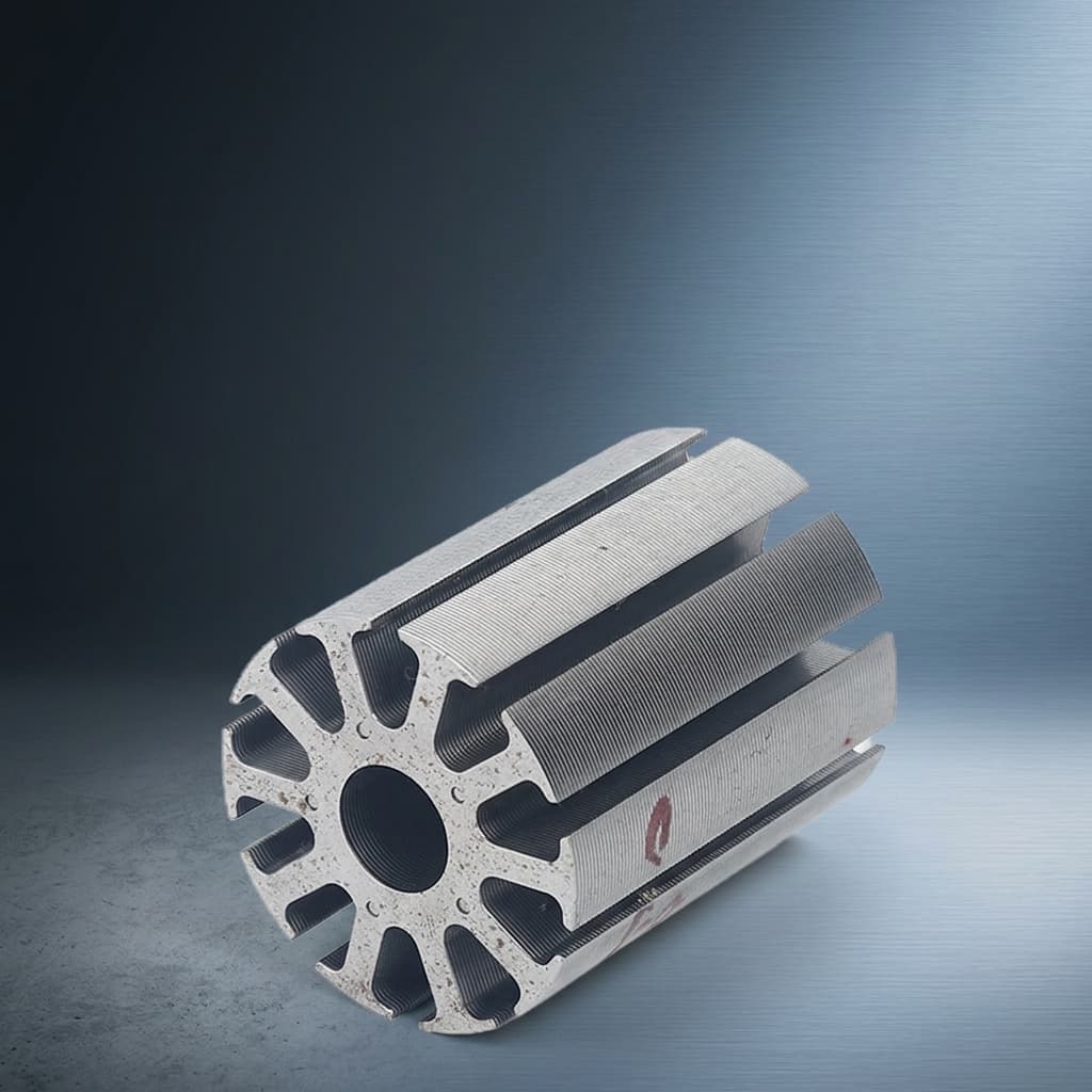
Silicon-steel axial flux motor stator iron core for lamination process comparison
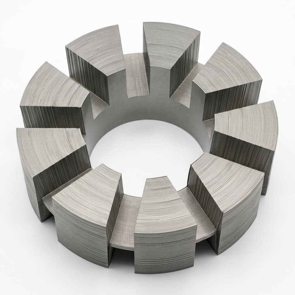
Segmented axial flux lamination stator reference for winding and stack locking discussion
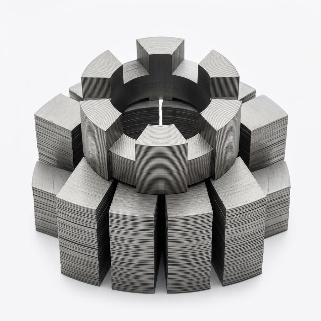
Layered axial lamination module reference for bonding and winding access review

Buyer FAQ

When should an AFPM buyer choose laminations instead of SMC?

Laminations can be attractive for low-frequency, high-permeability designs where the magnetic path and winding method fit a silicon-steel process. SMC is stronger when 3D flux, high frequency, net-shape geometry, or segmented assembly justify it.

What does dynamic punching and synchronized winding mean in an RFQ?

It means the tooth or slot features are controlled together with the strip or stack-forming route instead of being treated as a generic radial motor stamping. The RFQ should define slot geometry, pitch tolerance, OD/ID roundness, air-gap face, fixture concept, and inspection method.

How should polygon correction be specified?

Useful RFQs define the affected geometry, measurement datum, allowable pitch drift, OD/ID or runout target, sample inspection method, and whether the target is for bare stack, locked stack, or wound stator.

Can you quote core only and wound stator options separately?

Yes. The RFQ should state whether the buyer wants lamination core only, wound core, insulated stator, impregnated stator, or final tested assembly.

Can flat-wire or hairpin winding be reviewed?

Yes, when the buyer provides wire geometry, turn count, phase scheme, slot-fill target, lead exit, insulation build, thermal boundary, and prototype quantity. Flat-wire feasibility should be checked before slot geometry is frozen.

What insulation processes should be scoped?

Common RFQ scope items include self-bonding coating, resin varnish impregnation, vacuum-assisted varnish, epoxy powder coating, masking, cure condition, resistance, surge, insulation resistance, and Hi-pot test.

Do you guarantee final motor performance from the winding package?

No. We support component and process manufacturing scope. Final motor performance depends on buyer-side electromagnetic design, magnet system, rotor, cooling, drive, and validation.

What should ship with a wound stator prototype?

A practical shipment can include FAI, CMM/3D scan, slot pitch report, stacking factor, burr or edge-quality note, coating or varnish record, resistance and Hi-pot result when included, sample IDs, and packing notes.

Related Resources

  • SMC material data hub
  • Manufacturing & quality controls
  • Technology & Materials
  • Axial Flux Motor Core
  • AFPM SMC Stator
  • 3D Isotropic Flux Core
  • Magnetic Loss Validation
  • Axial Flux Stator Prototyping
  • Manufacturing & Quality
  • Engineering Resources
  • Contact / RFQ

Inquiry Email

[email protected]

Email app

Attach STEP/DXF/PDF plus frequency, flux density, sample quantity, annual forecast, and destination.

Instant Chat

+8618857971991

Chat on WhatsApp

Direct response from our engineering team.