WhatsApp
Axial Flux Core LogoAxial Flux Core
  • Home
  • Contact Us
Start inquiry
Axial Flux Core LogoAxial Flux Core

SMC axial flux motor core and AFPM stator OEM support for advanced electric drive teams.

Inquiry Email

[email protected]

Email app

Attach STEP/DXF/PDF plus frequency, flux density, sample quantity, annual forecast, and destination.

Instant Chat

+8618857971991

Chat on WhatsApp

Direct response from our engineering team.

Core Products
  • Product Portfolio
  • Axial Flux Motor Core
  • AFPM SMC Stator
  • SMC Stator Segments
  • YASA Segmented Stator Teeth
  • 3D Isotropic Flux Core
  • Lamination & Winding Services
  • Custom Compaction Tooling
Applications
  • Applications Overview
  • eVTOL Axial Flux Cores
  • Humanoid Joint Stators
  • Drone Propulsion Cores
  • EV Supercar AFPM Cores
  • Compact Generator Cores
Manufacturing & Quality
  • OEM Capability Hub
  • Technology & Materials
  • SMC Core Manufacturing
  • Manufacturing & Quality
  • Axial Flux Stator Prototyping
  • Compaction Tooling DFM
  • Magnetic Loss Validation
  • AFPM Manufacturing Route Tool
  • AFPM Core Design Checklist
  • AFPM Air Gap Design Tool
  • AFPM Cooling Design Tool
  • AFPM Cogging Torque Tool
Resources
  • Blog
  • About
  • Contact / RFQ
  • Engineering Resources
  • Privacy Policy
  • Cookie Policy
  • Terms of Service
© 2026 Axial Flux Core. All Rights Reserved.|Backed by Linkup Ai Co., Ltd. with axial flux core manufacturing support in Shenzhen and Dongguan, China.
Legal entity: Linkup Ai Co., Ltd.
← Back to Products

YASA Segmented Stator Teeth

YASA segmented stator teeth and SMC tooth modules for yokeless AFPM motors with demolding DFM, density control, holder retention, and encapsulation scope.

Target Buyer:For advanced motor OEM, Tier 1, and R&D sourcing teams using a buyer-owned YASA-style or yokeless segmented armature topology and needing manufacturable winding-ready tooth modules instead of a generic full-ring stator.
Request Custom QuoteDownload RFQ Templates
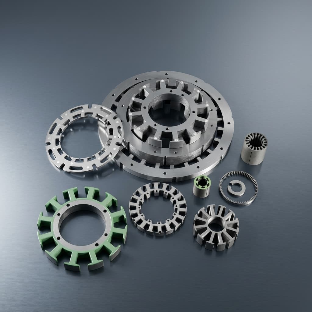
Independent SMC axial flux stator teeth arranged for yokeless armature review

Capability Highlights

  • Independent SMC tooth, tooth-pair, and carrier-ready module DFM for YASA-style dual-rotor yokeless AFPM layouts
  • High-tonnage compaction review for tooth-root radius, draft, ejection, green strength, and demolding microcrack control
  • Density-uniformity and tooth-to-tooth dimensional consistency checks before fixture, holder, or pilot release
  • Nonmagnetic holder, aluminum carrier, clamp ring, adhesive, resin encapsulation, potting, and housing-interface scope review
  • Winding clearance, bobbin fit, concentrated coil, flat-wire access, coating, and Hi-pot interface review before tooling

Typical Applications

  • YASA-style axial flux motors
  • Dual-rotor yokeless stator assemblies
  • High-slot-fill concentrated winding modules
  • Automotive and hypercar axial flux traction prototypes
  • eVTOL, robotics, and compact direct-drive AFPM programs

Engineering Focus

  • Tooth cross-section, press direction, draft angle, tooth-root radius, fragile wall features, ejection surface, and green-part handling
  • Density target, local density gradient, tooth-height repeatability, pitch datum, CMM/3D inspection access, and accumulated circular-pitch error
  • Demolding microcrack, chipped-edge, and root-transition risk tied to compaction pressure, corner radius, ejector strategy, and visual acceptance criteria
  • Axial magnetic pull, carrier retention, adhesive area, clamp load, potting route, nonmagnetic holder interface, and housing datum stack-up
  • Winding sequence, bobbin fit, flat-wire or concentrated-coil access, coating map, Hi-pot need, slot clearance, and impregnation or encapsulation boundary
  • IP boundary: manufacturing support for buyer-controlled YASA-style topology, not public disclosure or redesign of the buyer motor platform

Engineering Datasheet

Use this datasheet as an RFQ planning map for YASA-style and yokeless segmented stator teeth. Final geometry, density, retention, encapsulation, IP boundary, and validation acceptance must be confirmed from controlled buyer drawings and assembly context before tooling is frozen.

ParameterRFQ Planning RangeEngineering Note
Tooth module formatIndependent SMC tooth, tooth pair, grouped tooth module, carrier-ready tooth segment, or pre-coated winding-ready toothThe format should match winding sequence, holder concept, validation plan, and final retention method instead of only the electromagnetic model.
Parent stator envelopeOD 30-800 mm; ID 25 mm min.; axial height 5-110 mmThe individual tooth is reviewed against rotor clearance, holder geometry, and final stator stack-up.
Tooth count / circular pitch3-112 tooth positionsHigher counts increase the need for pitch fixtures, datum discipline, and cumulative error control.
Tooth geometry CTQsTooth height, pole-face width, root width, root radius, draft, air-gap face flatness, side-wall taper, and winding-window clearanceThese features drive torque-ripple risk, holder fit, winding access, green strength, and inspection strategy.
Demolding microcrack risk reviewTooth-root transition, sharp inner corners, tall thin walls, ejection face, parting line, compacted edge, and green-part transfer pathMicrocrack and chip risk should be screened during DFM and then tied to visual criteria, sample handling, and inspection records.
Density and mechanical route7.4-7.6 g/cm3 target where SMC grade, tooth geometry, and compaction route allowFinal density target depends on SMC grade, tooth height, wall thickness, compaction direction, green strength, and acceptable local variation.
Winding and insulation interfaceBobbin fit, pre-wound coil clearance, concentrated winding, flat-wire access, coating area map, coating thickness window, and optional Hi-pot scopeThe tooth can pass dimensional inspection but still fail assembly if coating, slot clearance, and winding sequence are not reviewed together.
Retention / holder interfaceNonmagnetic holder, aluminum carrier, clamp ring, adhesive land, overmold, potting, encapsulation, housing pocket, or buyer-defined fixtureMechanical retention must be validated against axial magnetic pull, vibration, thermal cycling, winding assembly, and inspection datum transfer.
Encapsulation / potting boundaryLoose tooth, carrier-ready tooth, holder-fitted sample, coated tooth, potted subassembly, or encapsulated stator moduleQuote pressed tooth, coating, holder fitting, adhesive, potting, encapsulation, and assembled-stator evidence as separate scope items.
Inspection and release packageFAI, CMM/3D scan, CTQ table, density or weight result, crack/chip visual check, coating or Hi-pot note, carrier-fit note, sample IDs, and traceabilityEngineering, sourcing, and supplier quality should agree which records are needed before sample release or pilot sourcing.

Process Notes

  • Start from the buyer-controlled tooth drawing and assembled stator model; the tooth cannot be quoted responsibly from a magnetic sketch alone.
  • Run DFM before tool freeze for draft, tooth-root radius, wall thickness, compaction direction, ejector strategy, fragile green-part handling, and visual microcrack criteria.
  • Use modular fixtures to validate circular pitch, tooth height, holder fit, carrier datum transfer, and winding clearance before pilot sampling.
  • Separate pressed tooth, machined datum, coating, holder fitting, winding support, adhesive, potting, encapsulation, and final assembly evidence so supplier quotes are comparable.
  • Keep YASA-style topology, motor IP, and public marketing claims separated from manufacturing feasibility and evidence-scope statements.

Validation Notes

  • Recommended buyer inputs: full stator assembly CAD, tooth drawing, target density, air gap, pull-force or vibration assumptions, thermal window, and winding access model.
  • Recommended reports: FAI, CMM/3D scan, CTQ table, weight or density check, visual crack/chip inspection, coating or Hi-pot result, carrier-fit notes, and traceability.
  • Retention, pull-force, vibration, thermal cycling, and encapsulation validation should be stated as project-specific scope rather than implied by the public page.
  • Acceptance values should reference drawing revision, sample IDs, fixture method, operating condition, and buyer validation gate instead of public planning ranges.

Evidence Pack

Audit-Ready Proof Package

For custom product RFQs, the useful proof is a controlled evidence package: drawings, material route, inspection records, validation scope, and sample acceptance notes.

Download templatesQuality controlsRequest evidence scope

Can the YASA-style tooth request be separated from buyer-owned motor IP?

Evidence to Prepare

NDA status, controlled tooth drawing, assembly envelope, topology context, revision ID, design owner, and manufacturing-only support boundary.

Acceptance Focus

Lets advanced OEMs discuss manufacturability without exposing or diluting their protected motor architecture.

Can demolding microcrack and chipped-edge risks be reviewed before tooling release?

Evidence to Prepare

DFM notes for root radius, draft, wall thickness, ejection face, compaction direction, green-part handling, visual criteria, and sample inspection plan.

Acceptance Focus

Reduces late discovery of fragile tooth-root defects after a high-cost compaction tool is already committed.

Can density uniformity and tooth-to-tooth consistency be proven with records?

Evidence to Prepare

CTQ table, CMM/3D scan, pitch fixture record, tooth-height report, density or weight baseline, sample IDs, and deviation log.

Acceptance Focus

Connects motor NVH, air-gap, torque-ripple, and magnetic repeatability concerns to auditable manufacturing evidence.

Can holder, carrier, adhesive, potting, and housing responsibility be audited before pilot samples?

Evidence to Prepare

Holder or carrier model, adhesive land map, clamp or housing datum plan, potting/encapsulation boundary, pull/vibration assumptions, and assembly sequence.

Acceptance Focus

Prevents loose tooth samples from passing inspection while the final yokeless stator assembly remains mechanically unresolved.

Can winding, coating, and insulation scope be validated against the same tooth geometry?

Evidence to Prepare

Bobbin or coil model, flat-wire clearance, coating area map, coating thickness expectation, mask notes, Hi-pot scope, and winding or impregnation sequence.

Acceptance Focus

Helps buyers avoid a tooth geometry that is magnetically attractive but difficult to wind, coat, pot, or qualify.

Buyer CheckpointEvidence to PrepareAcceptance Focus
Can the YASA-style tooth request be separated from buyer-owned motor IP?NDA status, controlled tooth drawing, assembly envelope, topology context, revision ID, design owner, and manufacturing-only support boundary.Lets advanced OEMs discuss manufacturability without exposing or diluting their protected motor architecture.
Can demolding microcrack and chipped-edge risks be reviewed before tooling release?DFM notes for root radius, draft, wall thickness, ejection face, compaction direction, green-part handling, visual criteria, and sample inspection plan.Reduces late discovery of fragile tooth-root defects after a high-cost compaction tool is already committed.
Can density uniformity and tooth-to-tooth consistency be proven with records?CTQ table, CMM/3D scan, pitch fixture record, tooth-height report, density or weight baseline, sample IDs, and deviation log.Connects motor NVH, air-gap, torque-ripple, and magnetic repeatability concerns to auditable manufacturing evidence.
Can holder, carrier, adhesive, potting, and housing responsibility be audited before pilot samples?Holder or carrier model, adhesive land map, clamp or housing datum plan, potting/encapsulation boundary, pull/vibration assumptions, and assembly sequence.Prevents loose tooth samples from passing inspection while the final yokeless stator assembly remains mechanically unresolved.
Can winding, coating, and insulation scope be validated against the same tooth geometry?Bobbin or coil model, flat-wire clearance, coating area map, coating thickness expectation, mask notes, Hi-pot scope, and winding or impregnation sequence.Helps buyers avoid a tooth geometry that is magnetically attractive but difficult to wind, coat, pot, or qualify.
Buyer Inputs That Unlock the Review
  • Controlled tooth STEP/DXF, 2D drawing, full stator assembly model, revision ID, NDA status, and buyer-owned IP boundary
  • Topology context: YASA-style or yokeless layout, rotor count, pole count, tooth count, air gap, axial stack height, and target speed range
  • CTQ dimensions: tooth height, tooth width, root radius, draft, datum surfaces, circular pitch, air-gap faces, and winding clearance
  • Retention method: nonmagnetic holder, aluminum carrier, clamp ring, adhesive, overmold, potting, encapsulation, housing feature, or buyer-defined fixture
Release Boundary

Any released claim should be tied to the buyer drawing, sample ID, material batch, inspection method, and agreed test condition instead of a generic marketing statement.

Key Evaluation Matrix

MetricTypical RangeWhy It Matters
Tooth-to-tooth consistencyCircular pitch, tooth height, air-gap face, and datum tolerance by controlled drawing and fixture planYASA stators accumulate small tooth errors into air-gap, noise, and torque-ripple risk.
Density uniformity7.4-7.6 g/cm3 target where geometry and SMC route allow, with local variation reviewed by sample evidenceUneven density can create magnetic variation, weak sections, and demolding defects in independent teeth.
Demolding risk controlRoot radius, draft, ejection, green strength, handling fixture, and crack/chip criteria reviewed before tool freezeIndependent teeth expose fragile root transitions that can fail before the motor program reaches magnetic testing.
Retention interfaceHolder, carrier, adhesive, clamp ring, housing pocket, overmold, potting, or encapsulation scope by projectA yokeless armature depends on a mechanical retention system because the teeth are not stabilized by a conventional back yoke.
Winding space gainBuyer coil and bobbin design dependentThe business case for segmented YASA teeth often depends on simpler winding and higher copper fill.
Release evidenceFAI, CMM/3D scan, density or weight check, crack/chip inspection, carrier-fit note, coating/Hi-pot note, and sample traceabilityEngineering and sourcing teams need a record package, not only a loose tooth sample, before approving pilot builds.

RFQ Checklist

  1. Controlled tooth STEP/DXF, 2D drawing, full stator assembly model, revision ID, NDA status, and buyer-owned IP boundary
  2. Topology context: YASA-style or yokeless layout, rotor count, pole count, tooth count, air gap, axial stack height, and target speed range
  3. CTQ dimensions: tooth height, tooth width, root radius, draft, datum surfaces, circular pitch, air-gap faces, and winding clearance
  4. Retention method: nonmagnetic holder, aluminum carrier, clamp ring, adhesive, overmold, potting, encapsulation, housing feature, or buyer-defined fixture
  5. Material route, SMC grade preference, density target, B-H or loss target, temperature window, coating or Hi-pot need, and allowed substitution boundary
  6. Winding process inputs: bobbin, pre-wound coil, concentrated winding, flat-wire route, impregnation, potting sequence, and mask/no-mask surfaces
  7. Validation package needed: FAI, CMM/3D scan, density or weight check, crack/chip inspection, carrier-fit notes, pull/vibration scope, and traceability
  8. Prototype quantity, pilot quantity, expected annual volume, sample approval gate, destination country, and required timeline

Risk Controls

  • Demolding microcracks appear at tooth roots or sharp transitions: Review root radius, draft, wall thickness, ejection face, green strength, compaction pressure, handling fixture, and visual criteria before tooling release.
  • Independent teeth shift under axial magnetic pull or vibration: Lock the holder, carrier, adhesive, potting, clamp, housing feature, and tooth datum scheme together with the expected axial load and vibration boundary.
  • Coils cannot be wound, inserted, or potted after tooth geometry is frozen: Review bobbin, flat-wire, concentrated winding, insulation, and potting clearance before sample tooling.
  • Density target is quoted as a single number while local geometry creates magnetic or mechanical variation: Tie density expectations to SMC grade, tooth geometry, compaction route, sample ID, weight or density method, and CTQ report.
  • A loose tooth sample passes inspection but fails the holder or encapsulated assembly: Define loose-tooth, carrier-ready, holder-fitted, potted, and encapsulated-module scope as separate sample and validation gates.
  • YASA-style language is interpreted as a public motor design claim: State that the page supports buyer-controlled YASA-style manufacturing DFM and does not disclose, license, or redesign buyer motor IP.

Product Gallery

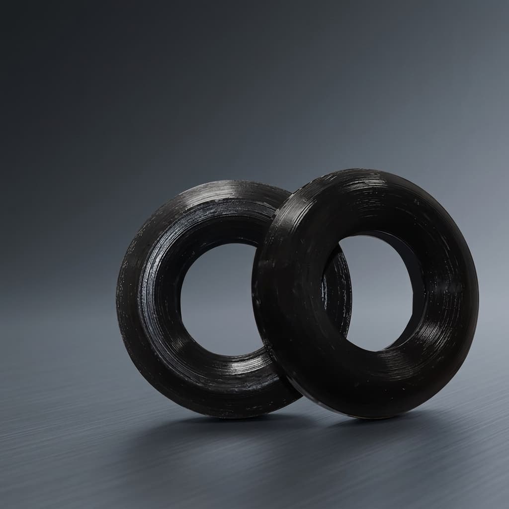
Pressed SMC stator tooth inserts high fidelity render
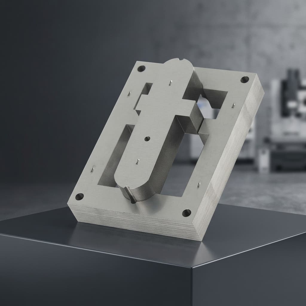
Segmented AFPM stator tooth block rendering
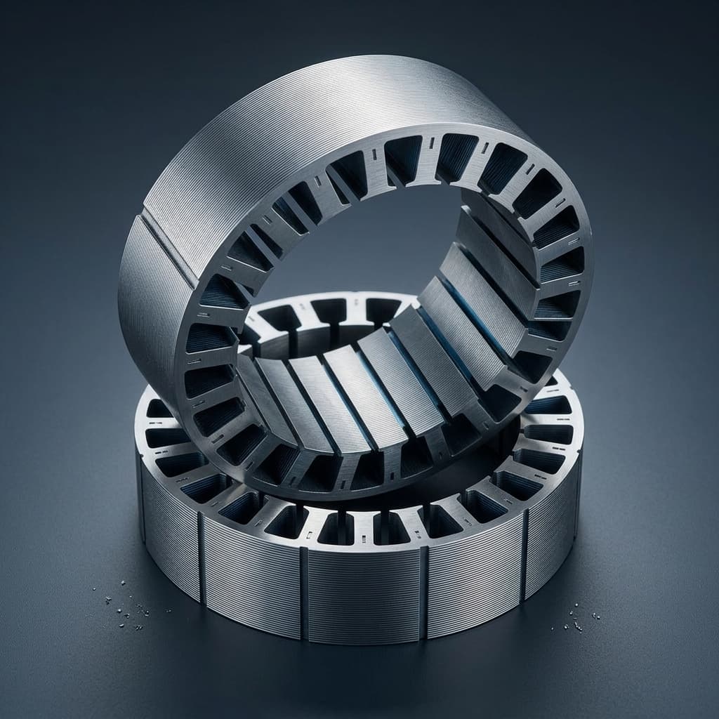
SMC segmented stator ring reference for carrier and encapsulation scope

Buyer FAQ

Can you manufacture YASA-style segmented stator teeth?

Yes, when the buyer provides the controlled tooth drawing, assembly envelope, retention concept, and validation criteria. We support SMC tooth-module manufacturing and DFM for buyer-controlled YASA-style or yokeless platforms, not buyer-owned motor IP.

Do you supply the holder or encapsulated assembly?

We can review holder, carrier, adhesive, potting, coating, and assembly-interface requirements as part of the RFQ. Scope should separate loose teeth, carrier-ready teeth, holder-fitted samples, and assembled or encapsulated stator modules.

Is this a complete motor design service?

No. The page covers SMC tooth-module manufacturing support for buyer-side YASA or yokeless AFPM platforms.

How do you address demolding microcracks in segmented teeth?

The first control is DFM: root radius, draft, wall thickness, press direction, ejection face, green strength, handling fixture, and visual crack/chip criteria should be reviewed before tooling. Sample release should then include inspection evidence tied to sample IDs.

Can each tooth be supplied winding-ready?

Yes, when coating, bobbin or coil clearance, flat-wire access, masking, Hi-pot scope, and potting or impregnation sequence are defined in the RFQ. Winding-ready scope should not be assumed from a loose pressed-tooth quote.

What evidence should be prepared for pilot approval?

A practical pilot package can include FAI, CMM or 3D scan, CTQ table, tooth-height and pitch checks, density or weight baseline, crack/chip inspection, coating or Hi-pot note, carrier-fit record, sample IDs, and traceability.

Are YASA-style dimensions guaranteed from the public planning range?

No. OD, ID, tooth count, height, density, and retention ranges are RFQ planning references. Final feasibility depends on buyer CAD, assembly envelope, SMC grade, compaction route, holder design, and validation method.

Related Resources

  • SMC material data hub
  • Manufacturing & quality controls
  • SMC Stator Segments
  • AFPM SMC Stator
  • Axial Flux Motor Core
  • Compaction Tooling DFM
  • Axial Flux Stator Prototyping
  • SMC Core Manufacturing
  • Technology & Materials
  • Manufacturing & Quality
  • Contact / RFQ

Inquiry Email

[email protected]

Email app

Attach STEP/DXF/PDF plus frequency, flux density, sample quantity, annual forecast, and destination.

Instant Chat

+8618857971991

Chat on WhatsApp

Direct response from our engineering team.