
Use SMC when the flux path is genuinely 3D
Axial flux stators, segmented teeth, flux concentrators, and compact actuators often combine axial, radial, and circumferential flux components.
Compare SMC material routes, density planning, B-H curve requirements, and high-frequency core-loss benchmarks before your AFPM stator or 3D flux core enters tooling.
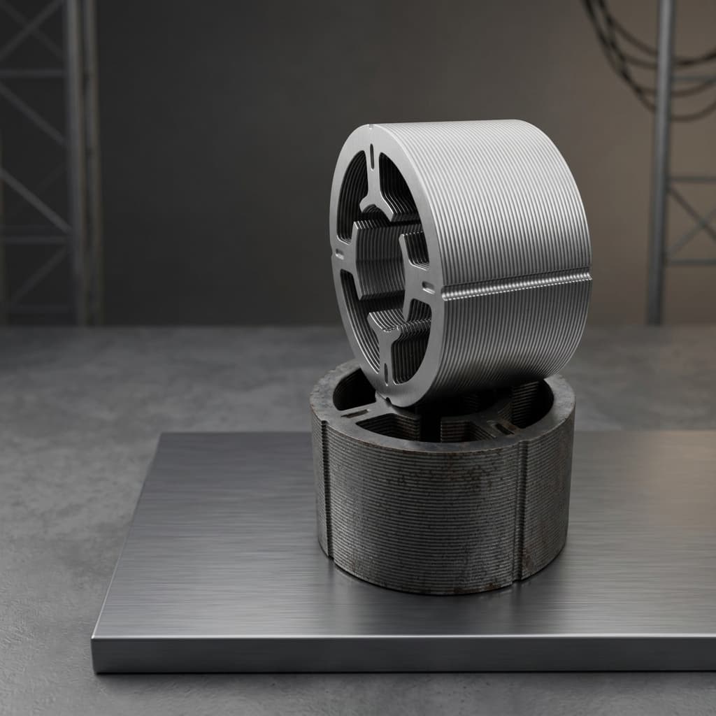
Axial flux stators, segmented teeth, flux concentrators, and compact actuators often combine axial, radial, and circumferential flux components.
Low-frequency permeability, high-frequency loss, thermal behavior, density, and tooling feasibility must be reviewed together.
Core loss and B-H data shift with sample geometry, compaction density, stress relief, coating, temperature, and test method.
The requirements brief asks for density, dimensions, iron loss, permeability, insulation, and thermal files. This gate map shows which inputs and supplier records should exist before material data is used for the next sourcing decision.
| Gate | Buyer Input | Supplier Return | Acceptance Boundary |
|---|---|---|---|
| Material Shortlist Gate | Candidate topology, expected frequency range, flux density target, temperature window, and 3D isotropic flux need. | Material route recommendation, comparison boundary, density planning window, and tests needed before sample release. | Accept only as an RFQ planning recommendation until sample geometry and test method are agreed. |
| Coupon or Prototype Gate | Coupon form, actual core geometry, sample ID rule, fixture assumptions, and target report format. | B-H, permeability, core-loss, density, insulation, and coating evidence tied to the test condition table. | Do not treat coupon data as final part acceptance when compaction density, heat route, coating, or geometry differs. |
| First Article Material Gate | Controlled drawing revision, material route baseline, CTQ dimensions, validation points, and deviation rules. | Lot-linked material record, density results, dimensional release note, and magnetic validation summary. | Release should reference drawing revision, sample ID, material lot, test condition, and buyer-approved deviations. |
| Pilot or Repeat-Order Gate | Change-control rule, batch retention requirement, reporting cadence, and receiving inspection expectations. | Traceability record, process route summary, inspection checkpoint results, and change notice for route shift. | Repeat lots should be compared against the last accepted baseline, not a generic material family. |
The final route should be selected from the motor operating point, geometry, required density, post-process, validation scope, and procurement traceability requirement.
| Route | Material Basis | Best Fit | Validation Focus |
|---|---|---|---|
| Baseline SMC Route | Somaloy 1P family or equivalent buyer-approved SMC grade | Cost-sensitive prototypes, baseline magnetic studies, and geometry feasibility programs. | Density, B-H curve, low-to-mid frequency loss, dimensional stability, and coating requirement review. |
| Strength-Focused SMC Route | Somaloy 3P family or equivalent strength-oriented route | Segmented teeth, vibration exposure, eVTOL or robotics samples, and handling-sensitive geometries. | Density uniformity, edge integrity, mechanical handling risk, insulation checks, and magnetic acceptance data. |
| High-Frequency Low-Loss Route | Somaloy 5P family or equivalent high-resistivity SMC route | High-speed AFPM machines, compact generators, drone propulsion, and designs above conventional lamination comfort zones. | Core loss at target frequency and flux density, B-H curve, thermal window, density, and sample geometry control. |
| Buyer-Specified Custom Route | Customer nominated powder, insulation system, coating, or traceability requirement | Automotive, aviation, research, or repeat-production programs where the material stack is already frozen. | Incoming material document, process route, inspection plan, test coupon method, and revision-controlled report package. |
These are RFQ planning fields, not universal guaranteed values. Released acceptance data should be tied to the selected material lot, part geometry, and agreed test method.
| Property | Planning Basis | Engineering Note |
|---|---|---|
| Pressed Density Target | 7.4-7.6 g/cm3 planning window | Density target is confirmed by material grade, geometry, press direction, compaction window, and the buyer acceptance method. |
| Magnetic Flux Behavior | 3D isotropic SMC magnetic path | Use SMC where axial, radial, and circumferential flux components all matter, then validate with the final sample or coupon test plan. |
| DC Permeability Review | B-H curve by grade, density, and heat-treatment route | A full curve is more useful than a single permeability number because local saturation and tooth-root loading drive AFPM behavior. |
| AC Loss Review | Frequency, flux density, waveform, and temperature dependent | Compare material options at the motor duty point instead of relying on one catalog number from a different sample geometry. |
| Electrical Insulation | Particle insulation plus project coating or Hi-pot scope | Core-side insulation, winding-side insulation, coating continuity, and corrosion protection should be separated in the RFQ. |
| Maximum Use Temperature Boundary | Buyer continuous and peak temperature plus material-route and coating limit | The useful operating window depends on the powder route, stress-relief process, coating, potting, and motor thermal path. |
The requirements brief calls for a material matrix with density, maximum use temperature, DC and AC permeability, 50 / 400 / 1000 Hz core loss, and B-H curve context. This table keeps those fields visible while separating public planning values from project-specific evidence.
| Required Field | Public Planning Disclosure | Release Evidence Needed |
|---|---|---|
| Material Grade Route | Somaloy 1P family for baseline screening, 3P family for strength-focused routing, 5P family for high-frequency low-loss routing, or buyer-nominated equivalent. | Buyer-approved grade or substitute rule, incoming material document, process route, and change-control boundary. |
| Density | 7.4-7.6 g/cm3 planning window, tied to route, geometry, compaction direction, and measurement method. | Sample-specific density result with inspection location, sample ID, material lot, and drawing revision. |
| Maximum Use Temperature | Capture continuous temperature, peak temperature, duty cycle, coating, potting, cooling path, and storage exposure before material lock. | Thermal condition note in the report package, with the accepted material route and insulation or coating boundary. |
| DC Permeability | Use a B-H curve request by grade, density, heat-treatment route, sample geometry, and H-field sweep range. | Released B-H curve or permeability table with fixture, temperature, sample form, density state, and report ID. |
| AC Permeability / Saturation | Declare frequency, waveform, flux-density target, temperature, and local saturation risk instead of quoting a single number. | Condition-specific permeability or saturation evidence tied to the selected coupon, segment, or full stator sample. |
| Core Loss at 50 / 400 / 1000 Hz | Use the 1.0 T planning matrix below to frame RFQ comparison between SMC and silicon-steel routes. | W/kg table with frequency, flux density, waveform, temperature, sample mass, geometry, fixture, and acceptance rule. |
| Insulation / Coating / Corrosion | Separate particle insulation, winding-interface coating, Hi-pot scope, corrosion exposure, and export storage risk. | Hi-pot, coating, visual, corrosion, or handling record connected to the same sample or batch baseline. |
Use these W/kg planning benchmarks to frame buyer questions; confirm production decisions with sample-specific test reports that state flux density, waveform, temperature, mass, and fixture.
Silicon steel can still be attractive at low frequency when 2D laminations match the magnetic path.
High-frequency eddy-current behavior starts to favor insulated-particle SMC in compact axial flux designs.
SMC becomes a strong candidate when the design combines high frequency, 3D flux, and compact packaging.
Boundary: these website values are comparison planning aids, not certified material specifications, customer release data, or a substitute for B-H and loss reports tied to actual samples.
Example planning curve format for RFQ discussion. The released curve should come from the selected material route and sample geometry, with density, temperature, fixture, and report ID stated.
This curve is illustrative. Treat the accepted B-H curve as a controlled report item linked to material route, sample ID, density, and test method.
The page can be useful without proprietary lab screenshots when it teaches buyers which conditions must be attached to each material number. These conditions should appear in the RFQ, prototype report, and buyer release checklist.
Required Condition
H-field sweep range, density, sample geometry, stress-relief route, temperature, and fixture method.
Why It Matters
Single permeability numbers hide saturation behavior at tooth roots and local flux concentrator features.
Required Condition
Frequency points, flux density points, waveform, temperature, sample form, and mass normalization.
Why It Matters
The same material can rank differently when duty point, coupon geometry, or thermal condition changes.
Required Condition
Target window, measurement method, inspection locations, compaction direction, and post-machining influence.
Why It Matters
Density drives magnetic response, mechanical handling risk, dimensional control, and repeatability.
Required Condition
Voltage, dwell time, coating scope, winding interface, corrosion protection, and allowed rework.
Why It Matters
Particle insulation, surface coating, winding insulation, and shipping corrosion are separate risks.
Required Condition
Continuous and peak temperature, thermal cycling, humidity, salt or corrosion exposure, potting, and storage.
Why It Matters
Material route depends on the full operating environment, not room-temperature magnetic data alone.
This is the trust layer for a material data hub without owned lab photos. Public copy should state what the data can support, and what it cannot replace, until real signed reports are approved for publication.
Can Support
Early screening, RFQ discussion, internal feasibility review, and validation request planning.
Cannot Replace
Final release, PPAP, warranty claims, regulated qualification, or production acceptance.
Can Support
Prototype review when the sample ID, material route, geometry, fixture, and test condition are stated.
Cannot Replace
Future repeat-order acceptance unless batch, process route, and change-control links are carried forward.
Can Support
Formal acceptance after both sides approve drawing, material, validation scope, and release limits.
Cannot Replace
Public website claims unless the customer permits anonymized disclosure and the scope is preserved.
Existing visuals are suitable for a first technical data center: permeability, high-frequency iron loss, density control, and SMC powder route. Replace with real lab charts and signed reports when customer-approved proof assets become available.

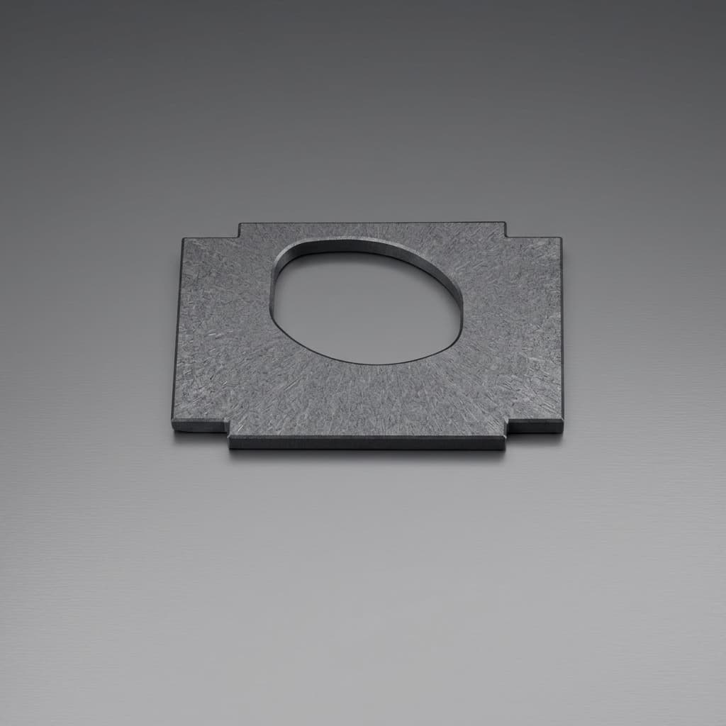

These public templates help teams agree what evidence should be prepared before prototype sampling, first article review, or pilot-lot release. They are not certificates, issued lab reports, or customer-specific records.
Reduces clarification loops by separating drawing, operating point, validation, and logistics inputs.
Download PDFPrevents generic material claims by tying validation data to the actual test condition and acceptance rule.
Download PDFKeeps material, process, inspection, and shipment records tied to one controlled program baseline.
Download PDFNo. This page provides RFQ planning data and a technical evaluation structure. Released specifications should be confirmed with the selected powder route, sample geometry, test method, and buyer acceptance criteria.
Yes. The RFQ can start from a buyer-selected grade, a target loss curve, or an operating point. The quote should then separate material sourcing, compaction, post-process, and validation scope.
Provide frequency, flux density, waveform, temperature, sample geometry, target report format, and whether the test should compare SMC against silicon steel or another baseline.
No. SMC is strongest when 3D magnetic paths, compact net-shape geometry, high-frequency loss control, or segmented manufacturing justify the route. Low-frequency 2D flux paths may still favor laminations.
A planning benchmark helps select a material route and define tests. A release report must tie measured data to sample ID, material lot, geometry, fixture, temperature, frequency, flux density, drawing revision, and buyer-approved acceptance rules.
At minimum, align the RFQ worksheet, magnetic validation report template, and material/process traceability fields before issuing sample purchase orders or treating a material route as production-ready.
Inquiry Email
Attach STEP/DXF/PDF plus frequency, flux density, sample quantity, annual forecast, and destination.