WhatsApp
Axial Flux Core LogoAxial Flux Core
  • Home
  • Contact Us
Start inquiry
Axial Flux Core LogoAxial Flux Core

SMC axial flux motor core and AFPM stator OEM support for advanced electric drive teams.

Inquiry Email

[email protected]

Email app

Attach STEP/DXF/PDF plus frequency, flux density, sample quantity, annual forecast, and destination.

Instant Chat

+8618857971991

Chat on WhatsApp

Direct response from our engineering team.

Core Products
  • Product Portfolio
  • Axial Flux Motor Core
  • AFPM SMC Stator
  • SMC Stator Segments
  • YASA Segmented Stator Teeth
  • 3D Isotropic Flux Core
  • Lamination & Winding Services
  • Custom Compaction Tooling
Applications
  • Applications Overview
  • eVTOL Axial Flux Cores
  • Humanoid Joint Stators
  • Drone Propulsion Cores
  • EV Supercar AFPM Cores
  • Compact Generator Cores
Manufacturing & Quality
  • OEM Capability Hub
  • Technology & Materials
  • SMC Core Manufacturing
  • Manufacturing & Quality
  • Axial Flux Stator Prototyping
  • Compaction Tooling DFM
  • Magnetic Loss Validation
  • AFPM Manufacturing Route Tool
  • AFPM Core Design Checklist
  • AFPM Air Gap Design Tool
  • AFPM Cooling Design Tool
  • AFPM Cogging Torque Tool
Resources
  • Blog
  • About
  • Contact / RFQ
  • Engineering Resources
  • Privacy Policy
  • Cookie Policy
  • Terms of Service
© 2026 Axial Flux Core. All Rights Reserved.|Backed by Linkup Ai Co., Ltd. with axial flux core manufacturing support in Shenzhen and Dongguan, China.
Legal entity: Linkup Ai Co., Ltd.
← Back to Products

Custom SMC Compaction Tooling

Custom SMC compaction tooling RFQ support for AFPM stators, covering press direction, 100-240 ton press fit, demolding, density risk, tool life, samples.

Target Buyer:For motor R&D, sourcing, and supplier-quality teams that already have an AFPM core or YASA tooth CAD package and need a manufacturable SMC compaction tool, sample plan, tooling cost boundary, and release evidence before purchase-order approval.
Request Custom QuoteDownload RFQ Templates
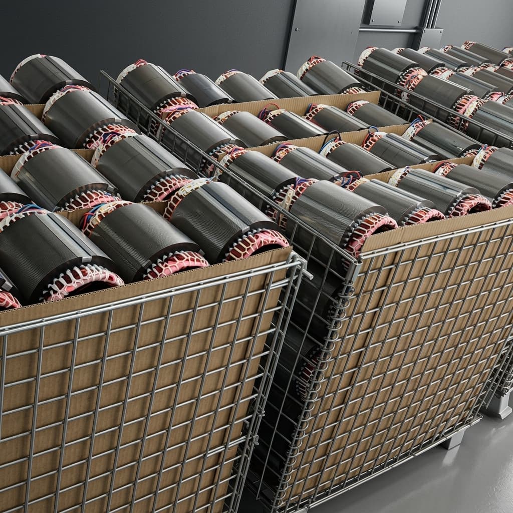
Axial flux stator compaction tooling equipment reference

Capability Highlights

  • Buyer-owned CAD is reviewed as a compaction-tooling problem: press direction, punch access, die split, ejection path, datum plan, and CTQs
  • 100-240 ton and higher powder-press fit can be discussed as a planning input when geometry, density target, material route, and tool envelope justify it
  • Demolding microcrack, chipped edge, thin tooth, high aspect-ratio, undercut, and sharp-corner risks are mapped before tool freeze
  • Density uniformity, green strength, ejection witness marks, machining allowance, coating, and post-process exposure are treated as tooling variables
  • Prototype, pilot-intent, and production tooling boundaries are separated for tool cost, ownership, maintenance, tool-life assumptions, and revision loops
  • Trial sample release can include FAI, CMM/3D scan, CTQ report, density or weight baseline, chip/burr notes, and optional magnetic validation scope

Typical Applications

  • Custom SMC stator tooling
  • AFPM core prototype tooling
  • YASA segmented tooth tooling
  • Near-net-shape 3D flux core tooling
  • Prototype-to-pilot tooling transfer
  • Buyer-owned IP and NDA-controlled tooling builds

Engineering Focus

  • DFM intake: STEP, DXF, controlled 2D drawing, revision ID, drawing owner, NDA status, datum scheme, CTQ list, and fixed versus adjustable features
  • Pressing strategy: compaction direction, fill behavior, punch and die access, die split, ejection sequence, draft, radius, and ejection witness-mark limits
  • Geometry risk: thin teeth, deep slots, sharp corners, high aspect ratios, undercuts, air-gap faces, segment edges, winding clearance, and fragile green-part handling
  • Material and density route: SMC grade, lubrication or release assumptions, 7.4-7.6 g/cm3 density target discussion, density gradient risk, and post-process thermal exposure
  • Tooling economics: DFM, prototype tool, pilot-intent tool, production tool, single or multi-cavity assumption, tool ownership, storage, maintenance, and revision-trigger rule
  • Release evidence: trial sample IDs, FAI, CMM or 3D scan, CTQ report, density or weight check, chip/burr review, coating note, optional magnetic data, and pilot transfer gate

Engineering Datasheet

Use this datasheet as an RFQ planning framework for custom SMC compaction tooling. Public ranges and equipment references are not production guarantees. Exact tool route, press fit, sample timing, ownership, tool life, inspection evidence, and pilot readiness should be confirmed after buyer-controlled CAD review or under NDA.

ParameterRFQ Planning RangeEngineering Note
Tooling phaseDFM, prototype tool, pilot tool, or production toolA learning tool, pilot-intent tool, and production tool can differ in tool steel, cavity strategy, maintenance, evidence package, cost, and revision control.
Supported part familiesAFPM stator rings, segmented stator blocks, YASA teeth, 3D flux pole pieces, compact yokes, and special SMC electromagnetic partsShape support depends on compaction direction, green strength, density target, ejection access, and buyer acceptance criteria.
Compaction route reviewSingle-direction, multi-level, segmented, or hybrid tooling feasibility discussionPress direction, powder fill, punch access, die split, compaction ratio, ejection, and green-part handling must be reviewed together.
Press and equipment-fit planning100-240 ton and higher press-fit discussion when part envelope, density target, and tooling layout require itTreat tonnage as a drawing-dependent tooling review item, not as a public promise that every part can be made on a specific press.
Part envelope reviewOD 30-800 mm; ID 25 mm min.; axial height 5-110 mm when applicableLarge rings, tall teeth, thin walls, and segmented teeth create different filling, ejection, inspection, and handling risks.
Fragile-feature risk mapThin teeth, deep slots, sharp transitions, high aspect ratios, undercuts, side-wall taper, root radius, air-gap face, and segment edgeDemolding microcracks and chipped edges are usually controlled by geometry, ejection route, draft/radii, green strength, and inspection criteria.
Density and green strengthMaterial and geometry dependent; 7.4-7.6 g/cm3 density target discussion where route allowsDensity uniformity affects magnetic performance, tool wear, crack risk, sample strength, and repeatability from prototype to pilot.
Ejection and release controlEjector surface, witness-mark tolerance, air-gap face protection, draft, corner relief, and handling route by drawingThe tool should be reviewed around how the green part leaves the die, not only around the final solid model.
Tooling commercial boundaryTool cost, sample charge, inspection charge, ownership, storage, maintenance, tool-life assumption, and revision-trigger ruleProcurement can compare tooling quotes only when hidden sample, maintenance, rework, and ownership assumptions are exposed.
Post-process allowanceMachining allowance, thermal process, coating, corrosion protection, deburr/chip criteria, and packaging methodPost-process needs can alter datum choice, surface condition, density measurement, and sample acceptance.
Trial sample release evidenceSample IDs, FAI, CMM/3D scan, CTQ report, density or weight baseline, visual chip/burr notes, optional magnetic data, and packing noteThe first tool loop should release evidence tied to drawing revision and buyer acceptance criteria, not loose samples alone.
Pilot transfer readinessAccepted revision, remaining risk list, inspection method, maintenance plan, packaging rule, pilot quantity, and change-control gateA prototype tool should not be treated as pilot-ready unless its evidence, maintenance, revision, and volume assumptions are documented.

Process Notes

  • Run tooling DFM before design freeze for press direction, die split, punch access, draft, corner radius, wall thickness, ejection, fragile features, and datum access.
  • Mark fixed magnetic features separately from adjustable manufacturing features so DFM changes do not accidentally change buyer-owned electromagnetic intent.
  • Separate DFM review, tool build, trial samples, FAI, density check, post-machining, coating, magnetic validation, maintenance, and storage in the RFQ.
  • Treat 100-240 ton press references as equipment-fit planning language until the actual drawing, material route, density target, and tool envelope are reviewed.
  • Any CAD revision after tool freeze should trigger a documented tooling impact review, rework decision, updated sample IDs, and repeated CTQ checks.

Validation Notes

  • Recommended buyer inputs: STEP, DXF, 2D drawing, revision ID, datum plan, CTQ list, material route, density target, fixed features, adjustable areas, annual volume, and sample deadline.
  • Recommended DFM records: compaction direction note, punch/die access sketch, fragile-feature risk map, demolding or ejection comments, density-risk notes, and open question list.
  • Recommended sample records: FAI, CMM/3D scan, CTQ dimensions, part weight or density baseline, visual chip/burr criteria, coating or post-process note, sample IDs, and deviation list.
  • Recommended commercial records: tool type, ownership, maintenance, storage, tool-life assumption, sample charges, inspection charges, revision-trigger rule, and pilot transfer gate.

Evidence Pack

Audit-Ready Proof Package

For custom product RFQs, the useful proof is a controlled evidence package: drawings, material route, inspection records, validation scope, and sample acceptance notes.

Download templatesQuality controlsRequest evidence scope

Can buyer-owned CAD be converted into a compaction route before design freeze?

Evidence to Prepare

STEP/DXF/2D drawing, revision ID, datum scheme, CTQs, press direction, die split, punch access, ejection path, and fixed-versus-adjustable feature list.

Acceptance Focus

Prevents tooling cost and sample timing from being approved before the geometry is manufacturable as an SMC pressed part.

Can press and equipment-fit assumptions be reviewed without overclaiming public capability?

Evidence to Prepare

Part envelope, projected area, density target, material route, tool layout, cavity assumption, 100-240 ton or higher press-fit discussion, and NDA-only equipment evidence when needed.

Acceptance Focus

Lets procurement discuss realistic tooling routes while avoiding public-page promises that may not match the final CAD.

Can demolding microcrack and chipped-edge risk be checked before samples ship?

Evidence to Prepare

Fragile-feature map, corner radius notes, draft or relief notes, air-gap face protection, ejection witness criteria, visual chip/burr standard, and sample inspection plan.

Acceptance Focus

Targets the failure modes that matter for YASA teeth and thin AFPM stator features before the buyer spends a full tooling budget.

Can density uniformity and green strength be tied to the trial sample evidence?

Evidence to Prepare

Material route, density target, weight baseline, local-density concern list, green handling route, post-process exposure, sample IDs, and optional magnetic validation scope.

Acceptance Focus

Connects tooling decisions to magnetic performance and mechanical robustness instead of relying on geometry screenshots.

Can tool cost, ownership, maintenance, tool life, and revision loops be separated clearly?

Evidence to Prepare

Tooling cost line, sample charge, inspection charge, tool type, ownership term, maintenance boundary, storage rule, tool-life assumption, and revision-trigger language.

Acceptance Focus

Gives engineering, quality, and procurement a shared approval basis before prototype, pilot, or production tooling is ordered.

Buyer CheckpointEvidence to PrepareAcceptance Focus
Can buyer-owned CAD be converted into a compaction route before design freeze?STEP/DXF/2D drawing, revision ID, datum scheme, CTQs, press direction, die split, punch access, ejection path, and fixed-versus-adjustable feature list.Prevents tooling cost and sample timing from being approved before the geometry is manufacturable as an SMC pressed part.
Can press and equipment-fit assumptions be reviewed without overclaiming public capability?Part envelope, projected area, density target, material route, tool layout, cavity assumption, 100-240 ton or higher press-fit discussion, and NDA-only equipment evidence when needed.Lets procurement discuss realistic tooling routes while avoiding public-page promises that may not match the final CAD.
Can demolding microcrack and chipped-edge risk be checked before samples ship?Fragile-feature map, corner radius notes, draft or relief notes, air-gap face protection, ejection witness criteria, visual chip/burr standard, and sample inspection plan.Targets the failure modes that matter for YASA teeth and thin AFPM stator features before the buyer spends a full tooling budget.
Can density uniformity and green strength be tied to the trial sample evidence?Material route, density target, weight baseline, local-density concern list, green handling route, post-process exposure, sample IDs, and optional magnetic validation scope.Connects tooling decisions to magnetic performance and mechanical robustness instead of relying on geometry screenshots.
Can tool cost, ownership, maintenance, tool life, and revision loops be separated clearly?Tooling cost line, sample charge, inspection charge, tool type, ownership term, maintenance boundary, storage rule, tool-life assumption, and revision-trigger language.Gives engineering, quality, and procurement a shared approval basis before prototype, pilot, or production tooling is ordered.
Buyer Inputs That Unlock the Review
  • STEP, DXF, 2D PDF drawing, revision ID, drawing owner, NDA status, datum scheme, CTQ list, and sample acceptance language
  • Target SMC material route, density target, operating frequency, flux density, temperature window, post-process route, coating, and corrosion-protection expectation
  • Fixed features that cannot move: air-gap face, tooth pitch, tooth width, slot depth, segment interface, winding window, mounting datum, and assembly clearance
  • Adjustable DFM areas: draft, radius, corner relief, machining allowance, ejection witness marks, non-contact surfaces, and chip-tolerant edges
Release Boundary

Any released claim should be tied to the buyer drawing, sample ID, material batch, inspection method, and agreed test condition instead of a generic marketing statement.

Key Evaluation Matrix

MetricTypical RangeWhy It Matters
Tooling phaseDFM, prototype tool, pilot tool, production toolEach tooling phase carries different cost, evidence, tool-life, maintenance, revision, and pilot-readiness assumptions.
Press fit and tonnage planning100-240 ton and higher discussion by projected area, density target, part envelope, and tool layoutEquipment-fit discussion helps screen feasibility, but final press selection must stay tied to buyer CAD and process route.
Density uniformityMaterial, compaction direction, local geometry, green strength, and post-process route dependentDensity affects permeability, strength, crack risk, magnetic consistency, and repeatability across sample and pilot lots.
Demolding and chip riskThin teeth, deep slots, corner radius, draft, ejection surface, and handling route dependentMicrocracks and chipped air-gap faces can make a visually acceptable SMC sample unusable in motor assembly.
Tool life and maintenance boundaryPrototype learning tool, pilot-intent tool, production tool, maintenance rule, and revision stability dependentTool-life language controls long-term cost and prevents a prototype tool from being mistaken for production-ready tooling.
Trial release evidenceFAI, CMM/3D scan, CTQ report, density or weight baseline, chip/burr note, optional magnetic data, and sample IDsA tooling project is only useful when trial parts can be approved by engineering, supplier quality, and procurement from the same evidence package.

RFQ Checklist

  1. STEP, DXF, 2D PDF drawing, revision ID, drawing owner, NDA status, datum scheme, CTQ list, and sample acceptance language
  2. Target SMC material route, density target, operating frequency, flux density, temperature window, post-process route, coating, and corrosion-protection expectation
  3. Fixed features that cannot move: air-gap face, tooth pitch, tooth width, slot depth, segment interface, winding window, mounting datum, and assembly clearance
  4. Adjustable DFM areas: draft, radius, corner relief, machining allowance, ejection witness marks, non-contact surfaces, and chip-tolerant edges
  5. Press and equipment-fit assumptions: expected part envelope, compaction direction, tonnage planning discussion, die height, cavity count, and sample-tool space constraints
  6. Tooling phase: DFM-only review, prototype learning tool, pilot-intent tool, production tool, single-cavity or multi-cavity path, and expected revision loop
  7. Commercial boundary: tooling cost line, sample charge, inspection charge, tool ownership, storage, maintenance, tool-life assumption, and revision-trigger rule
  8. Trial sample quantity, FAI or CTQ report requirement, density or weight check, optional magnetic validation, pilot lot size, annual forecast, and destination packaging
  9. Buyer-side milestone: design freeze date, prototype build date, pilot gate, purchasing approval process, and required public or NDA-only evidence format

Risk Controls

  • Buyer locks geometry before SMC manufacturing review: Run DFM before design freeze and mark press direction, punch access, die split, ejection path, fragile features, datum scheme, and adjustable surfaces.
  • Public tonnage language is mistaken for a guaranteed production promise: Keep 100-240 ton and higher press references as planning language until CAD, density target, projected area, and tool layout are reviewed.
  • Demolding creates microcracks, chipped teeth, or damaged air-gap faces: Review draft, radii, corner relief, ejection surfaces, handling route, green strength, and visual chip/burr criteria before tool freeze.
  • Density gradients are discovered only after motor testing fails: Tie density or weight baseline, local feature risk, material route, and optional magnetic validation to the trial sample release package.
  • Tooling cost hides sample charges, inspection, maintenance, storage, or ownership: Quote tool build, trial parts, FAI, validation, maintenance, storage, buyer ownership, and revision-trigger rules as separate scope lines.
  • Prototype learning tool is treated as pilot or production-ready: Create a pilot transfer gate that records accepted revision, open risks, inspection method, maintenance plan, forecast volume, and change-control rule.
  • CAD changes after tool freeze are absorbed without revalidation: Require revision impact review, tooling rework decision, updated sample IDs, and repeated CTQ checks for changed features.

Product Gallery

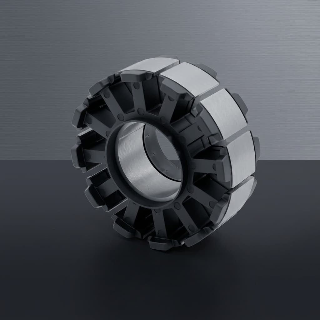
Custom SMC compaction tool geometry reference for ring core ejection and datum review
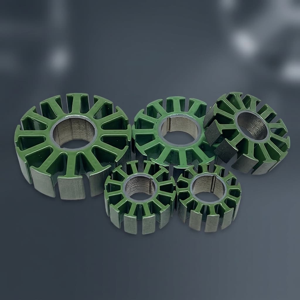
AFPM stator tooling sample reference for density uniformity and fragile feature DFM
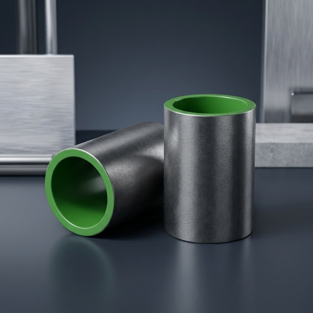
SMC tooling sleeve reference for punch access and green part release planning

Buyer FAQ

What is custom SMC compaction tooling for AFPM stators?

It is the drawing-specific tool and process route used to compact insulated iron powder into an axial flux stator core, segment, YASA tooth, or 3D flux feature. The useful RFQ discussion covers compaction direction, die split, punch access, ejection, density, sample evidence, and commercial tooling terms.

Can you help modify the core drawing for manufacturability?

Yes. We can review geometry and suggest manufacturing-facing changes such as radius, draft, relief, machining allowance, or non-critical ejection surfaces while preserving the buyer magnetic intent where possible.

What is needed for first tooling DFM feedback?

A STEP file, 2D drawing or CTQ list, target material route, density target, fixed features, adjustable features, sample objective, volume assumption, deadline, and NDA status are enough for a structured first review.

Do public 100-240 ton press references guarantee my part can be produced?

No. They are planning references for equipment-fit discussion. Final press route depends on projected area, material, density target, part height, tool layout, cavity count, ejection route, and accepted sample evidence.

Can tooling be quoted separately from trial samples?

Yes. Tool build, trial samples, FAI, density checks, optional magnetic validation, maintenance, storage, and ownership terms should be separated so procurement can approve the scope cleanly.

How do you handle demolding microcrack risk?

The practical controls are DFM review for thin features, draft, radii, relief, ejection path, green strength, handling route, air-gap face protection, and visual chip or crack criteria tied to sample inspection.

Can density uniformity be guaranteed from CAD alone?

No. Density depends on geometry, compaction direction, material route, pressing conditions, local features, and post-process route. It should be checked through trial samples with weight, density, or optional magnetic evidence when required.

Who owns the compaction tool after payment?

Tool ownership, storage, maintenance, modification rights, tool-life assumptions, and end-of-project handling should be written into the quote or purchase agreement before the tooling PO.

What happens if CAD changes after tooling starts?

Changed features should trigger a tooling impact review covering rework, cost, schedule, sample IDs, and repeated CTQ checks before new trial samples or pilot transfer are approved.

Related Resources

  • SMC material data hub
  • Manufacturing & quality controls
  • AFPM SMC Stator
  • YASA Segmented Stator Teeth
  • 3D Isotropic Flux Core
  • Compaction Tooling DFM
  • SMC Core Manufacturing
  • Manufacturing & Quality
  • Technology & Materials
  • Engineering Resources
  • Contact / RFQ

Inquiry Email

[email protected]

Email app

Attach STEP/DXF/PDF plus frequency, flux density, sample quantity, annual forecast, and destination.

Instant Chat

+8618857971991

Chat on WhatsApp

Direct response from our engineering team.