WhatsApp
Axial Flux Core LogoAxial Flux Core
  • Home
  • Contact Us
Start inquiry
Axial Flux Core LogoAxial Flux Core

SMC axial flux motor core and AFPM stator OEM support for advanced electric drive teams.

Inquiry Email

[email protected]

Email app

Attach STEP/DXF/PDF plus frequency, flux density, sample quantity, annual forecast, and destination.

Instant Chat

+8618857971991

Chat on WhatsApp

Direct response from our engineering team.

Core Products
  • Product Portfolio
  • Axial Flux Motor Core
  • AFPM SMC Stator
  • SMC Stator Segments
  • YASA Segmented Stator Teeth
  • 3D Isotropic Flux Core
  • Lamination & Winding Services
  • Custom Compaction Tooling
Applications
  • Applications Overview
  • eVTOL Axial Flux Cores
  • Humanoid Joint Stators
  • Drone Propulsion Cores
  • EV Supercar AFPM Cores
  • Compact Generator Cores
Manufacturing & Quality
  • OEM Capability Hub
  • Technology & Materials
  • SMC Core Manufacturing
  • Manufacturing & Quality
  • Axial Flux Stator Prototyping
  • Compaction Tooling DFM
  • Magnetic Loss Validation
  • AFPM Manufacturing Route Tool
  • AFPM Core Design Checklist
  • AFPM Air Gap Design Tool
  • AFPM Cooling Design Tool
  • AFPM Cogging Torque Tool
Resources
  • Blog
  • About
  • Contact / RFQ
  • Engineering Resources
  • Privacy Policy
  • Cookie Policy
  • Terms of Service
© 2026 Axial Flux Core. All Rights Reserved.|Backed by Linkup Ai Co., Ltd. with axial flux core manufacturing support in Shenzhen and Dongguan, China.
Legal entity: Linkup Ai Co., Ltd.
← Back to Products

AFPM SMC Stator

AFPM SMC stator manufacturing for axial flux motors with 3D tooth geometry, winding clearance review, resin insulation coating, and validation planning.

Target Buyer:For motor R&D, sourcing, and supplier-quality teams comparing SMC, silicon steel lamination, and PCB stator routes for compact axial flux platforms before tooling commitment.
Request Custom QuoteDownload RFQ Templates
AFPM stator concept for SMC manufacturing

Capability Highlights

  • Circular, sector/fan, one-piece, segmented, and tooth-module AFPM stator geometry review
  • RFQ planning envelope for OD 30-800 mm, ID 25 mm min., 5-110 mm axial height, and 3-112 slots
  • Winding-ready review covering slot opening, bobbin or pre-wound tooth route, flat-wire feasibility, resin insulation coating, and Hi-pot scope
  • Air-gap and thermal stack-up review across flatness, parallelism, circular pitch, potting, bonding, and curing boundaries
  • Prototype-to-pilot evidence package for engineering, sourcing, and supplier-quality review

Typical Applications

  • Axial flux permanent magnet motors
  • Compact robotic joint stators
  • Drone and eVTOL propulsion stators
  • Compact generators and pancake motor platforms
  • High-performance EV, in-wheel, and hypercar motor concepts

Engineering Focus

  • Topology and format: single-rotor, dual-rotor, yokeless, one-piece ring, segmented stator, sector/fan segment, and individual tooth-module concepts
  • Geometry risk: tooth height, yoke thickness, chamfered 3D teeth, slot opening, circular pitch, winding access, air-gap datum, draft, and corner radius
  • Winding and insulation interface: bobbin, concentrated winding, pre-wound tooth, flat-wire or hairpin feasibility, resin coating area, varnish or impregnation boundary, potting, and Hi-pot need
  • Material and process route: insulated iron-powder SMC or buyer-nominated Somaloy family, density target around 7.4-7.6 g/cm3 where geometry and compaction route allow, ejection path, and local density balance
  • Validation method: FAI, CMM or 3D scan, density or weight check, B-H curve, core-loss test, coating inspection, insulation or Hi-pot result, thermal boundary note, traceability, and packing record

Engineering Datasheet

The AFPM SMC stator datasheet is an RFQ planning guide, not a catalog guarantee. Final geometry, tolerances, density, coating, winding interface, and validation scope are confirmed against buyer CAD, assembly method, and operating point.

ParameterRFQ Planning RangeEngineering Note
Supported AFPM stator shapesOne-piece circular ring, sector/fan segment, segmented stator, individual tooth module, or optimized 3D tooth/yoke featureShape choice should be reviewed against topology, compaction direction, demolding, winding access, and air-gap datum control.
Outer / inner diameter envelopeOD 30-800 mm; ID 25 mm min.Final limits depend on air-gap datum, press direction, tool strength, tooth geometry, and local density balance.
Axial height5-110 mmTall teeth or deep slots need density gradient, green strength, ejection, coating coverage, and handling review.
Slot count planning range3-112 slotsSlot opening, copper fill, bobbin clearance, tooth pitch, and potting space should be reviewed before tooling.
Tooth and yoke geometryChamfered tooth, reduced yoke thickness, tapered 3D tooth, slot opening, tooth pitch, draft, corner radius, and datum face reviewComplex tooth geometry can help axial-flux packaging, but it also drives compaction pressure, ejection, micro-crack, and density-risk review.
Winding access envelopeBobbin winding, concentrated winding, pre-wound tooth, post-assembly winding review, or hairpin/flat-wire feasibility reviewThis page should not promise a fixed slot-fill gain. The practical winding path and insulation clearance must be proven from the buyer assembly.
Resin insulation coatingCoating before winding, coating area map, target thickness window, masking boundary, visual criteria, and Hi-pot scope when requiredCoating can protect winding-adjacent SMC surfaces, but it changes slot clearance, heat path, and acceptance criteria.
Mechanical bonding / curing / potting boundaryAdhesive bonding, curing support, potting boundary, carrier or housing interface, and fixture note by project scopeThe quote should separate pressed core supply from coating, bonding, potting, fixture, or assembled-stator responsibility.
Material and density routeInsulated iron-powder SMC, buyer-nominated Somaloy family, or performance-selected SMC route; 7.4-7.6 g/cm3 target where geometry and process allowDensity, permeability, strength, and loss targets must be tied to the selected grade, compaction route, heat treatment, and magnetic test condition.
Critical interface controlsFlatness, parallelism, circular pitch, and datum scheme per drawingAFPM output is sensitive to axial air-gap variation, stator-to-rotor stack-up, and cumulative segment pitch error.
Inspection and release packageFAI, CMM or 3D scan, CTQ dimensions, density or weight check, B-H, core loss, coating note, Hi-pot when scoped, traceability, and packing recordEngineering, sourcing, and SQE should agree which records are needed before sample shipment.

Process Notes

  • Freeze topology and winding route before tooling release: one-piece ring, segmented stator, tooth module, bobbin, pre-wound tooth, concentrated winding, or flat-wire/hairpin feasibility route.
  • Separate pressed SMC stator supply, machining, resin insulation coating, winding preparation, potting, bonding, curing, assembly fixture, magnetic validation, and export packaging in the quote.
  • Review air-gap datum, flatness, parallelism, circular pitch, slot opening, coating thickness, and potting boundary before judging a CAD model as manufacturable.
  • Treat public-page ranges as RFQ planning guidance. Do not use them as guaranteed limits for every buyer-owned stator geometry.

Validation Notes

  • Recommended buyer inputs: topology, slot/pole count, electrical frequency, flux-density target, duty cycle, waveform, speed, temperature limit, cooling method, winding route, and insulation target.
  • Recommended reports: FAI, CMM or 3D scan, CTQ dimensions, density or weight check, B-H curve, core-loss report, coating note, Hi-pot or insulation test when scoped, traceability, and packing record.
  • Acceptance values should reference controlled drawing revision, sample IDs, operating condition, test method, and agreed coating or winding boundary rather than public planning ranges.

Evidence Pack

Audit-Ready Proof Package

For custom product RFQs, the useful proof is a controlled evidence package: drawings, material route, inspection records, validation scope, and sample acceptance notes.

Download templatesQuality controlsRequest evidence scope

Can the AFPM topology and winding route be reviewed before SMC tooling is released?

Evidence to Prepare

Assembly section, topology type, slot/pole count, winding route, slot opening, bobbin or tooth-module concept, air-gap datum, CTQ list, and DFM notes.

Acceptance Focus

Prevents the common failure where a pressed stator looks correct but cannot be wound, insulated, potted, or assembled into the motor stack.

Can material grade, density target, and magnetic validation be tied to the real operating point?

Evidence to Prepare

SMC or Somaloy grade, density target, frequency, waveform, flux-density target, temperature condition, B-H requirement, core-loss method, and sample IDs.

Acceptance Focus

Lets R&D compare SMC, lamination, and PCB stator routes using the same motor condition instead of generic material claims.

Can insulation coating, Hi-pot, potting, bonding, and curing scope be audited before samples ship?

Evidence to Prepare

Coating area map, coating thickness target, masking boundary, Hi-pot scope, adhesive or potting boundary, thermal-path note, visual criteria, and inspection record.

Acceptance Focus

Reduces late-stage assembly failures caused by coating thickness, slot-clearance loss, thermal-path change, or unclear supplier responsibility.

Can engineering, sourcing, and SQE receive the same AFPM stator release package?

Evidence to Prepare

FAI, CMM or 3D scan, CTQ table, density or weight record, B-H or core-loss report when scoped, coating or Hi-pot note, traceability, sample acceptance sheet, and packing record.

Acceptance Focus

Turns early AFPM stator samples into records that support design review, supplier approval, pilot sourcing, and repeat-order control.

Buyer CheckpointEvidence to PrepareAcceptance Focus
Can the AFPM topology and winding route be reviewed before SMC tooling is released?Assembly section, topology type, slot/pole count, winding route, slot opening, bobbin or tooth-module concept, air-gap datum, CTQ list, and DFM notes.Prevents the common failure where a pressed stator looks correct but cannot be wound, insulated, potted, or assembled into the motor stack.
Can material grade, density target, and magnetic validation be tied to the real operating point?SMC or Somaloy grade, density target, frequency, waveform, flux-density target, temperature condition, B-H requirement, core-loss method, and sample IDs.Lets R&D compare SMC, lamination, and PCB stator routes using the same motor condition instead of generic material claims.
Can insulation coating, Hi-pot, potting, bonding, and curing scope be audited before samples ship?Coating area map, coating thickness target, masking boundary, Hi-pot scope, adhesive or potting boundary, thermal-path note, visual criteria, and inspection record.Reduces late-stage assembly failures caused by coating thickness, slot-clearance loss, thermal-path change, or unclear supplier responsibility.
Can engineering, sourcing, and SQE receive the same AFPM stator release package?FAI, CMM or 3D scan, CTQ table, density or weight record, B-H or core-loss report when scoped, coating or Hi-pot note, traceability, sample acceptance sheet, and packing record.Turns early AFPM stator samples into records that support design review, supplier approval, pilot sourcing, and repeat-order control.
Buyer Inputs That Unlock the Review
  • Controlled 2D drawing, 3D STEP file, assembly section, revision ID, drawing owner, and NDA status
  • AFPM topology: single rotor, dual rotor, yokeless, one-piece stator, segmented stator, or tooth-module assembly
  • OD, ID, axial height, pole count, slot count, tooth shape, yoke thickness, slot opening, datum scheme, and CTQ tolerances
  • Winding route: bobbin, concentrated winding, pre-wound tooth, hairpin or flat-wire concept, slot-fill target, coating area, and potting boundary
Release Boundary

Any released claim should be tied to the buyer drawing, sample ID, material batch, inspection method, and agreed test condition instead of a generic marketing statement.

Key Evaluation Matrix

MetricTypical RangeWhy It Matters
Stator formatOne-piece circular ring, sector/fan segment, segmented stator, or tooth-module SMC statorThe format drives tooling cost, winding access, fixture strategy, serviceability, pitch control, and supplier responsibility.
Winding clearanceBobbin, concentrated winding, pre-wound tooth, post-assembly winding, or hairpin/flat-wire feasibility reviewA good magnetic geometry can still fail if copper, insulation, coating, and potting cannot physically fit.
Air gap controlFlatness, parallelism, circular pitch, datum scheme, and stator-to-rotor stack-up per drawingAFPM output is highly sensitive to axial air gap variation and stator flatness.
Density and material routeBuyer-nominated or performance-selected SMC route; 7.4-7.6 g/cm3 target where geometry and compaction allowDensity affects permeability, loss behavior, mechanical strength, and repeatability of thin tooth or sector features.
Insulation and thermal boundaryResin coating, optional Hi-pot, varnish or impregnation boundary, potting, bonding, curing, and cooling-interface reviewThe stator core has to survive winding, voltage stress, thermal exposure, and assembly release rather than only pass dimensional review.

RFQ Checklist

  1. Controlled 2D drawing, 3D STEP file, assembly section, revision ID, drawing owner, and NDA status
  2. AFPM topology: single rotor, dual rotor, yokeless, one-piece stator, segmented stator, or tooth-module assembly
  3. OD, ID, axial height, pole count, slot count, tooth shape, yoke thickness, slot opening, datum scheme, and CTQ tolerances
  4. Winding route: bobbin, concentrated winding, pre-wound tooth, hairpin or flat-wire concept, slot-fill target, coating area, and potting boundary
  5. Operating point: torque, speed, electrical frequency, flux-density target, bus voltage, cooling condition, duty cycle, and temperature limit
  6. Required evidence package: FAI, CMM or 3D scan, density, B-H, core loss, resin coating, Hi-pot, traceability, packaging, and sample acceptance records
  7. Prototype quantity, pilot quantity, target annual volume, destination country, packaging constraints, and deadline

Risk Controls

  • Winding cannot be assembled after the SMC part is made: Review winding path, slot access, bobbin option, and potting sequence before tool release.
  • Flat-wire or hairpin slot-fill target conflicts with SMC geometry or coating thickness: Treat slot fill as a buyer-validated target and check wire path, corner radius, coating window, and thermal path before quoting the winding interface.
  • Air-gap faces are not controlled early enough: Define datum faces, flatness, parallelism, circular pitch, rotor stack-up, and inspection method before sample approval.
  • Coating, potting, bonding, or curing scope changes final clearance: Separate each post-process in the quote and require coating-area maps, thickness expectations, masking boundary, and acceptance criteria.
  • Buyer compares SMC and laminations by the wrong metric: Separate low-frequency permeability, high-frequency loss, 3D flux benefit, and mechanical assembly cost.
  • Public ranges are treated as guaranteed specifications: Tie all acceptance values to controlled drawing revision, material route, sample ID, inspection method, and project-specific validation records.

Product Gallery

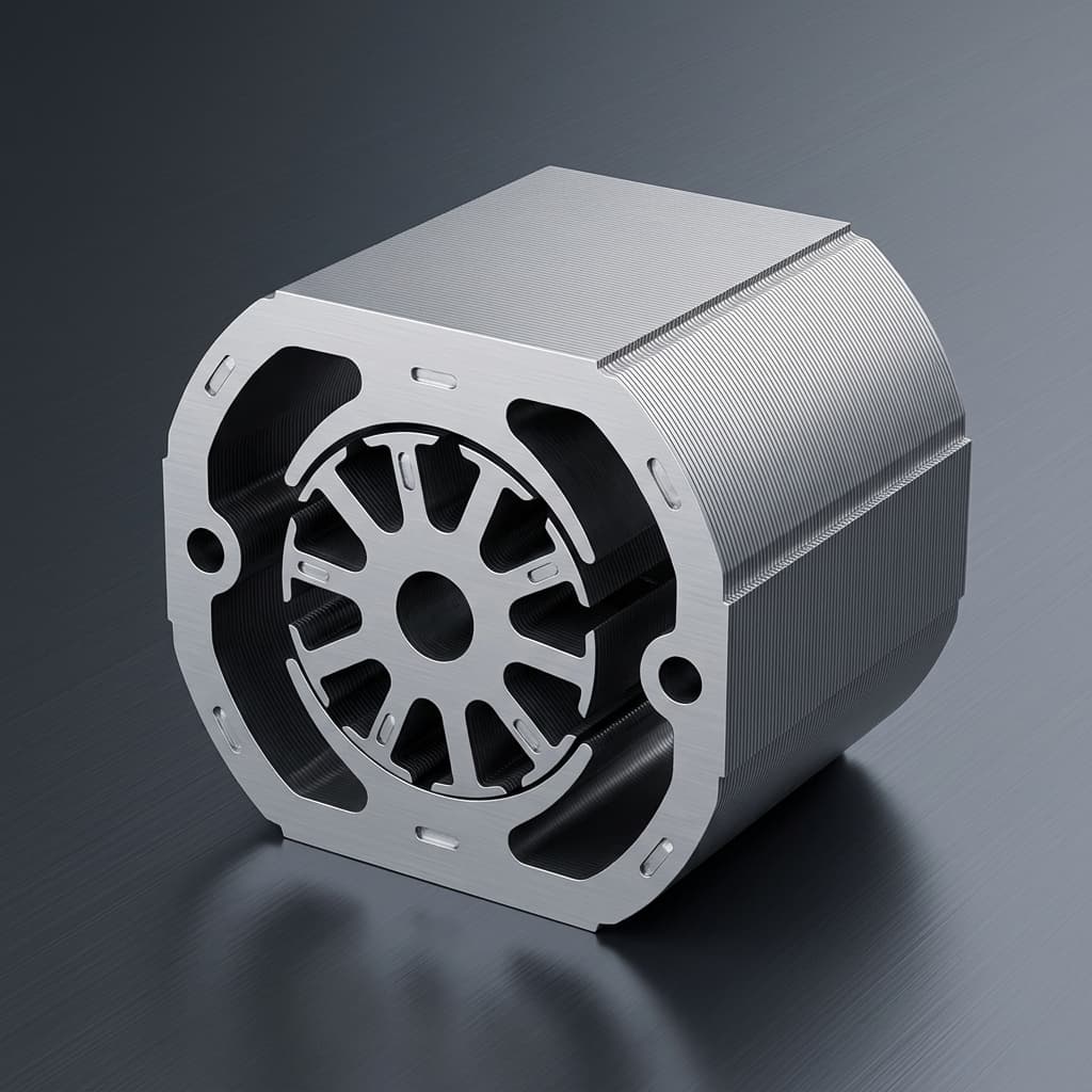
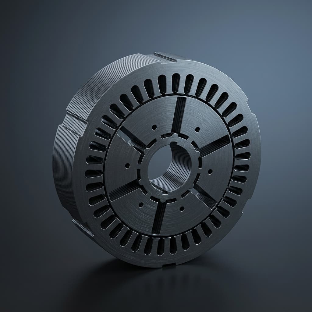
Axial flux stator assembly reference
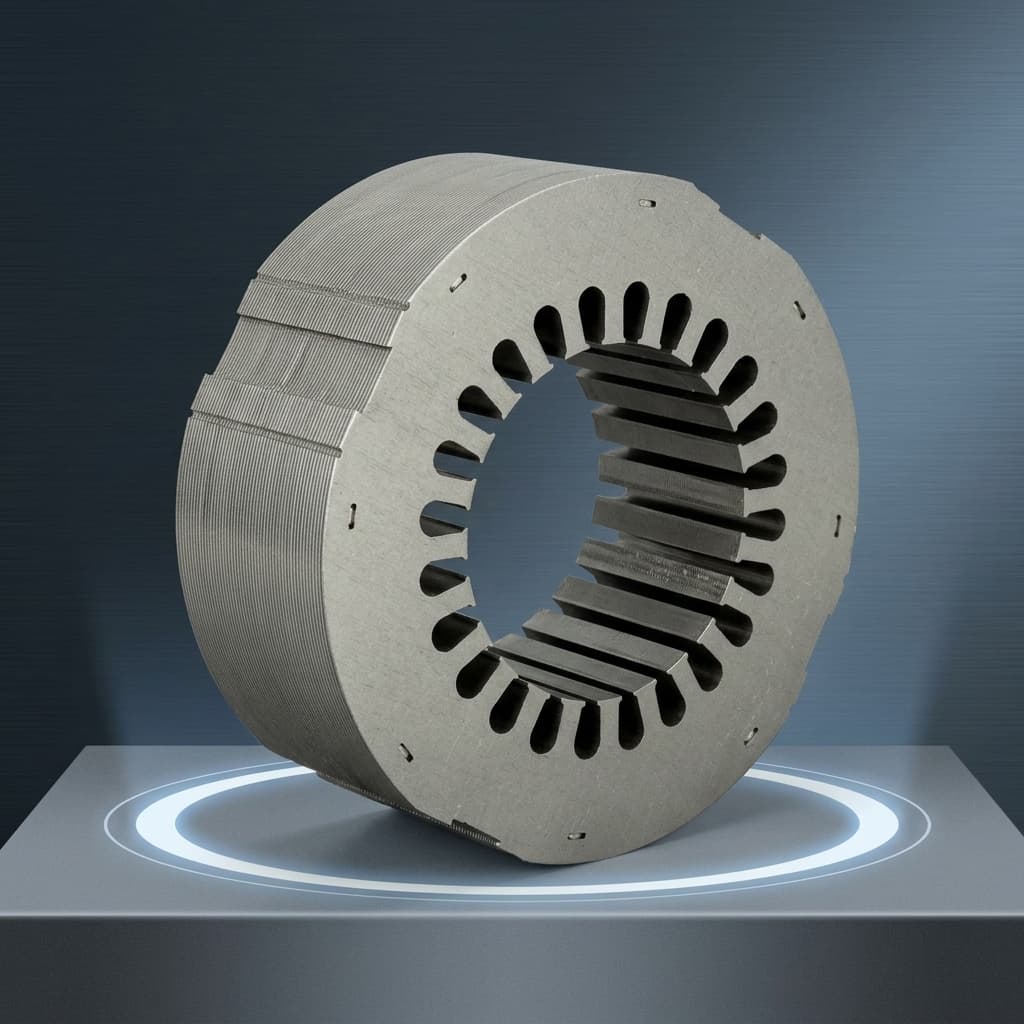
High fidelity render of solid SMC stator core
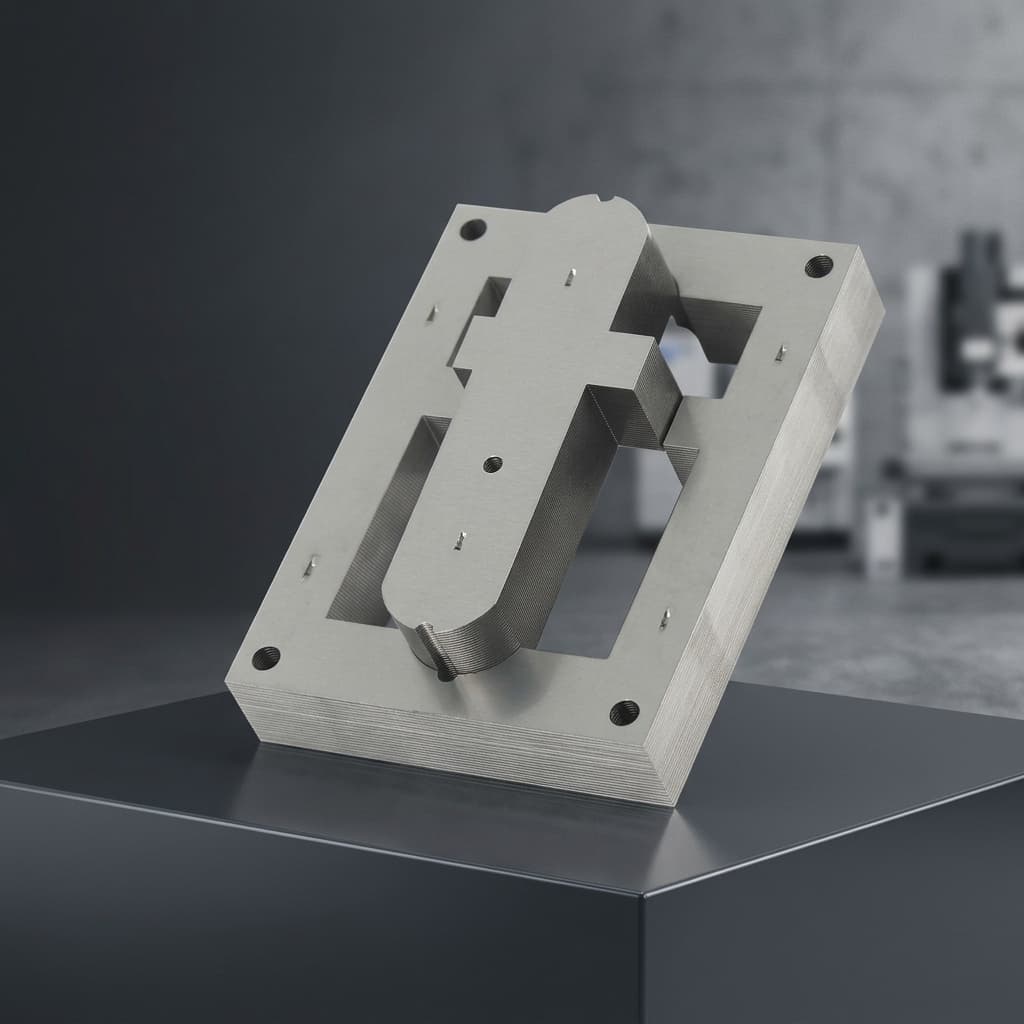
AFPM stator tooth module render for SMC compaction DFM

Buyer FAQ

Can you quote a segmented AFPM stator?

Yes. Send the segment CAD, full stator assembly, datum scheme, winding route, retention method, pitch tolerance, and required inspection points so tooling and tolerance risk can be reviewed.

What AFPM stator shapes can be reviewed?

The RFQ scope can review circular one-piece stators, sector or fan-shaped segments, segmented stator rings, individual tooth modules, and optimized 3D tooth or yoke geometry. Final feasibility depends on press direction, demolding, density balance, and winding access.

Can resin insulation coating and Hi-pot testing be included?

They can be scoped when the buyer provides coating areas, thickness expectations, voltage or Hi-pot requirement, masking boundary, and visual criteria. Coating must be reviewed with slot clearance and thermal path before release.

Can you support flat-wire, hairpin, or concentrated winding routes?

The page supports winding-interface review and project-scope discussion. The practical supply boundary must state whether the quote includes pressed SMC parts only, coating, winding preparation, winding/impregnation support, potting, or assembled-stator evidence.

Are the OD, ID, height, and slot-count ranges guaranteed?

No. OD 30-800 mm, ID 25 mm minimum, 5-110 mm axial height, and 3-112 slots are RFQ planning ranges. Final acceptance depends on buyer CAD, material grade, compaction route, tolerances, coating, winding interface, and validation method.

What evidence should come with AFPM SMC stator samples?

A useful sample package normally includes FAI, CMM or 3D scan data, CTQ dimensions, density or weight check, B-H or core-loss results when scoped, coating or Hi-pot notes, traceability, sample IDs, and packing records.

Related Resources

  • SMC material data hub
  • Manufacturing & quality controls
  • Axial Flux Motor Core
  • SMC Stator Segments
  • YASA Segmented Stator Teeth
  • Axial Flux Stator Prototyping
  • SMC Core Manufacturing
  • Lamination & Winding Services
  • Contact / RFQ

Inquiry Email

[email protected]

Email app

Attach STEP/DXF/PDF plus frequency, flux density, sample quantity, annual forecast, and destination.

Instant Chat

+8618857971991

Chat on WhatsApp

Direct response from our engineering team.