WhatsApp
Axial Flux Core LogoAxial Flux Core
  • Home
  • Contact Us
Start inquiry
Axial Flux Core LogoAxial Flux Core
Design & DFM Resources

AFPM Core Design Checklist

Use this AFPM (axial flux permanent magnet) core design checklist to score electromagnetic, structural, thermal, and manufacturing risks before committing to expensive tooling.

Evidence reviewed July 29, 2026. Source dates and limitations are listed below the assessor before any tooling decision.

Start AssessorRead Design Guidelines
13
readiness checks
6
critical gates
6
reviewed sources
AFPM Core Design Readiness Assessor
Evaluate your axial flux core design maturity across electromagnetic, mechanical, thermal, and manufacturing domains.
Interactive Checklist

Magnetic & Electromagnetic

Mechanical & Assembly

Thermal Management

Manufacturing & DFM

Readiness Assessment

Completion Score0%

0 of 14 items validated

0 of 7 critical gates covered

Empty State: Start With Critical Gates
No checklist items are selected yet. The assessor is ready and waiting for your design evidence.

Missing Critical Gates

  • 3D flux path simulated (critical for SMC cores)
  • Lower relative permeability (100-700) vs. steel accounted for
  • Iron loss vs. frequency validated
  • Air gap deflection dynamically simulated under axial load
  • Core thermal conductivity accounted for (especially for SMC)
  • Supplier draft, minimum wall thickness, and ejection limits verified
  • Length-to-wall-thickness ratio screened for density gradients

Next Actions

Recommended next step

Start with the red Critical gates: 3D FEA, material curves, air-gap deflection, thermal path, and SMC DFM limits.

If the result is inconclusive

If you do not have the evidence yet, use the action plan below as the minimum replacement path.

Read Design Guidelines

Critical Design Guardrails

3D flux demands 3D simulation

Axial flux topologies using SMC cores rely on true 3D flux paths. 2D FEA approximations will overestimate torque density and underpredict saturation in the stator yoke due to SMC's lower relative permeability (typically 100-700) compared to steel.

Evidence S1, S2, S3: Electromagnetic simulation boundaries and SMC material curves.

Axial deflection is catastrophic

High attractive forces between rotor and stator require extreme structural rigidity. If dynamic deflection exceeds the air gap clearance (often < 1mm), catastrophic failure occurs.

Evidence S6: Mechanical assembly tolerances and load cases.

SMC thermals require active mitigation

SMC has isotropic but lower thermal conductivity (~20-30 W/mK) compared to the in-plane conductivity of laminations (~40-50 W/mK). Hot spots at the tooth root must be mitigated via potting or direct cooling.

Evidence S3, S5: Material datasheet benchmarks and AFPM thermal guide limits.

Compaction limits drive core geometry

For SMC powder compaction, straight walls risk cracking during ejection. Draft, wall thickness, aspect ratio, and ejection direction must be reviewed before tool release.

Evidence S1, S4: Powder metallurgy DFM screening boundaries.

Evidence Ledger and Method Flow

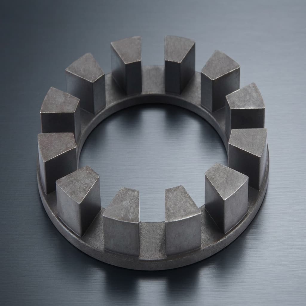
AFPM core design checklist visual showing an SMC axial flux stator core for DFM review
SMC axial flux stator core geometry frames the checklist gates for electromagnetic, thermal, mechanical, and DFM evidence.
AFPM Design Workflow1. ConceptTopology & Sizing2. Simulation3D FEA & Thermals3. DFM CheckDrafts & Tolerances4. ReleaseTooling KickoffIterative design workflow for Axial Flux PM Motors

Use the workflow after the assessor: close critical gates, attach evidence IDs, then decide whether the design is ready for RFQ, prototype, or rework.

Traceable Source Ledger

Dates show when the source was reviewed for this page; vendor PDFs and design centers can change without notice.

IDSourceUsed ForReviewed
S1Hoganas - Somaloy powder solutions for SMC applicationsSupports SMC motor-core positioning, 3D magnetic behavior, near-net-shape PM process fit, and supplier-specific DFM review.July 29, 2026
S2JMAG International and Hoganas - SMC in motor designSupports the warning that SMC core design should be evaluated with motor simulation and material data rather than steel-core assumptions.July 29, 2026
S3Hoganas - Somaloy 3P material dataBenchmarks published SMC material properties used as screening context; buyer geometry still requires project-specific test coupons.July 29, 2026
S4Metal Powder Industries Federation - Design Resource CenterProvides powder-metallurgy design framing for pressing, ejection, tolerances, and manufacturability review.July 29, 2026
S5AxialFluxCore - AFPM thermal management and cooling guideInternal evidence layer for heat-path, potting, direct cooling, and thermal validation questions.July 22, 2026
S6AxialFluxCore - manufacturing quality evidenceInternal supplier-quality lens for dimensional inspection, first-article review, and RFQ evidence handoff.July 29, 2026
SMC vs. Laminated Route Decision
Route selection should be made on matched operating conditions, not on a generic material preference.
DimensionSMC RouteLaminated RouteDecision Rule
Flux path fitBest fit when the AFPM core uses 3D flux, tooth shaping, or segmented geometry.Best fit when flux can stay in a mostly 2D laminated path with acceptable stacking and edge-stress control.Choose SMC only when the geometry and frequency benefit justify supplier-specific material validation.
Simulation evidenceRequires B-H curve, loss map, density target, compaction direction, and local saturation review.Requires grade, lamination thickness, coating, stack factor, cut-edge effect, and bonding method.Do not release either route from a generic material label; require traceable test conditions.
Manufacturing riskDraft, ejection, wall thickness, density gradient, curing, and secondary grinding can dominate cost.Progressive tooling, lamination burr, stacking, bonding, annealing, and flatness can dominate cost.Send manufacturability assumptions with the first RFQ, not after the geometry is frozen.
Prototype routeUse coupons, simplified segments, machined blanks, or soft tooling before hard compaction dies.Use laser or wire-cut stacks, then validate edge loss and stack retention before progressive dies.Pick the prototype route that proves the highest-risk physics first.
Prototype Release Gates
Pass evidence must be attached before the checklist score is used for tooling or RFQ decisions.
GatePass EvidenceStop Condition
Electromagnetic3D FEA with local saturation, leakage, frequency-specific iron loss, and source-specific material curves.2D model only, missing B-H curves, or flux density assumptions copied from laminated steel.
MechanicalAir-gap stack-up, rotor/stator stiffness, bearing growth, axial pull, and dynamic deflection margin.Static clearance is treated as enough proof or deflection margin is smaller than tolerance growth.
ThermalLoss map, hot-spot model, potting/interface data, cooling path, and named duty-cycle boundary.Only nominal power is supplied or cooling is selected before loss and interface evidence exists.
ManufacturingDraft/ejection review, density gradient plan, wall-thickness review, tolerance stack, and inspection datum plan.Geometry cannot be compacted, measured, or retained without secondary operations not priced in the RFQ.

Risks, Limits, and Mitigations

RiskImpactLikelihoodMitigation
Using the checklist as final design approvalHighMediumTreat the score as a readiness screen; release only after FEA, samples, inspection, and supplier DFM evidence agree.
SMC route chosen for a steel-like geometryMediumMediumCompare SMC and laminated routes with the same torque, frequency, tolerance, and validation basis.
Critical air-gap and axial-load evidence missingHighMediumAdd stiffness, runout, bearing growth, thermal expansion, and debris clearance checks before prototype release.
Tooling CAPEX committed before DFM closureHighHighUse coupons, segmented samples, or soft tooling until draft, density, wall thickness, and inspection datums are signed off.

Engineering Action Plan

1. Electromagnetic Validation

  • Confirm 3D FEA solver is used for flux path analysis.
  • Verify iron losses at maximum operating frequency (e.g., > 400Hz).
  • Check local flux density to ensure no deep saturation (< 1.8T for SMC).

2. Mechanical & Structural

  • Calculate static and dynamic axial attractive forces.
  • Set air gap tolerances and verify housing/bearing stiffness.
  • Define core retention mechanisms (clamping, potting, overmolding).

3. Thermal Analysis

  • Account for actual material thermal conductivity.
  • Simulate peak continuous torque temperature at the winding-tooth interface.
  • Design cooling path (e.g., water jacket, direct oil cooling).

4. Manufacturing (DFM)

  • Verify supplier-specific draft, wall-thickness, ejection, and secondary-operation limits.
  • Screen length-to-wall-thickness ratio and density gradients with supplier DFM input.
  • Plan segmentation when press capacity, density uniformity, or air-gap control cannot be proven.
  • Perform tolerance stack-up analysis for the complete assembly.

Simulation vs. Reality Limits

Electromagnetic predictions

Known:The checklist covers essential simulation steps like 3D FEA and saturation limits.
Unknown:Actual B-H curve variations due to specific local compaction densities.
Action:Validate with physical samples; do not rely purely on nominal datasheet curves.

Mechanical deflection

Known:Axial forces can be calculated statically.
Unknown:Dynamic resonances and housing compliance under thermal expansion.
Action:Perform full structural-thermal-magnetic coupled analysis.

SMC Compaction Integrity

Known:Overall bulk component density and average permeability.
Unknown:Local density drops at deep tooth roots and microscopic insulation coating breakage from over-compaction.
Action:Perform 3D density mapping simulation or request segmented test pieces from PM supplier.
Require Expert Review?
Send us your STEP files and operating targets.

Our engineering team provides confidential DFM reviews, identifying pressing risks, dimensional stack-ups, and alternative tooling routes.

Request DFM Assessment

Ready for supplier-specific AFPM core review?

Send CAD, material route, duty cycle, tolerance stack, and the checklist gaps so AxialFluxCore can screen SMC tooling, inspection, and prototype risk before RFQ release.

Request DFM AssessmentReview Quality Evidence

Frequently Asked Questions

Design & Simulation

Manufacturing & Tolerances

Sourcing & RFQ

Related Resources

Manufacturing Route EstimatorAFPM Air Gap Design CalculatorAFPM Cooling Design CalculatorAFPM Cogging Torque CalculatorAxial Flux Motor CoreAFPM SMC StatorSMC Materials & Core Loss DataQuality Assurance & InspectionRequest DFM Engineering Review
Axial Flux Core LogoAxial Flux Core

SMC axial flux motor core and AFPM stator OEM support for advanced electric drive teams.

Inquiry Email

[email protected]

Email app

Attach STEP/DXF/PDF plus frequency, flux density, sample quantity, annual forecast, and destination.

Instant Chat

+8618857971991

Chat on WhatsApp

Direct response from our engineering team.

Core Products
  • Product Portfolio
  • Axial Flux Motor Core
  • AFPM SMC Stator
  • SMC Stator Segments
  • YASA Segmented Stator Teeth
  • 3D Isotropic Flux Core
  • Lamination & Winding Services
  • Custom Compaction Tooling
Applications
  • Applications Overview
  • eVTOL Axial Flux Cores
  • Humanoid Joint Stators
  • Drone Propulsion Cores
  • EV Supercar AFPM Cores
  • Compact Generator Cores
Manufacturing & Quality
  • OEM Capability Hub
  • Technology & Materials
  • SMC Core Manufacturing
  • Manufacturing & Quality
  • Axial Flux Stator Prototyping
  • Compaction Tooling DFM
  • Magnetic Loss Validation
  • AFPM Manufacturing Route Tool
  • AFPM Core Design Checklist
  • AFPM Air Gap Design Tool
  • AFPM Cooling Design Tool
  • AFPM Cogging Torque Tool
Resources
  • Blog
  • About
  • Contact / RFQ
  • Engineering Resources
  • Privacy Policy
  • Cookie Policy
  • Terms of Service
© 2026 Axial Flux Core. All Rights Reserved.|Backed by Linkup Ai Co., Ltd. with axial flux core manufacturing support in Shenzhen and Dongguan, China.
Legal entity: Linkup Ai Co., Ltd.