
SMC Stator Core Machining vs. Net-Shape Compaction: Surface Particle Smearing, Eddy Current Traps, Chemical Etching, and Prototyping Sourcing Economics
Compare SMC stator machining and net-shape compaction, assess surface smearing and eddy losses, and plan prototype validation costs. Request a drawing review.
Decision-level summary: SMC stator machining vs. net-shape compaction is a choice about what the prototype must prove. Machining can support geometry changes without a dedicated tooth die, but a machined blank does not automatically reproduce production magnetic properties. Cutting can deform iron particles across insulating boundaries, creating conductive surface bridges and additional eddy current paths. Net-shape compaction reduces the need to cut active magnetic faces, while introducing its own tooling, density and ejection constraints. Qualify the actual route before using prototype losses to approve a motor design. Chemical etching is a potential surface-treatment option requiring grade-specific validation, not a universal restoration step.
Published and reviewed: November 7, 2026. Scope: Global B2B axial flux motor engineers, prototype buyers and Supplier Quality Engineers (SQEs). This is a sourcing and validation guide for soft magnetic composite (SMC) stator cores. It combines cited manufacturer information, a proposed engineering qualification workflow and an explicitly hypothetical cost model. It contains no first-party machining trials, measured loss-recovery data or supplier quotations. Material grade, compaction history, heat treatment, waveform and finished geometry remain application-specific.
Preparing a prototype RFQ? Request a drawing-led engineering review with CAD, operating points and required quantities. For product context, see our AFPM SMC stator solutions.
1. The Prototyping Dilemma: Tooling NRE vs. Machined Blanks
Early axial flux motor development often needs several tooth-shoe widths, winding clearances or retention details before the geometry stabilizes. A dedicated compaction tool ties spending to one design revision. Machining a suitable blank can offer more flexibility, provided the blank dimensions, material condition and machining capacity are available. Neither stock availability nor a delivery date should be assumed from a material trade name.
Start by defining the experiment. A winding-fit sample may only need the correct envelope, edge condition and handling strength. A magnetic validation sample also needs traceable material properties and a surface condition representative of the intended motor. A production approval sample must additionally represent the serial tooling and process. Treating all three as the same purchase creates misleading comparisons.
Request separate prices for blanks, programming, fixtures, machining, any surface treatment and inspection. A machined route can avoid a dedicated compaction die while still carrying non-recurring engineering (NRE) charges. Conversely, an existing supplier tool or a simpler tooth design can change the economics of compaction. There is no universal tooth count at which one route becomes mandatory.
Record quantities as individual teeth, complete stators and spare samples. The conversion depends on teeth per stator and the motor topology. Comparing one supplier's price per tooth with another supplier's price per stator can overwhelm any real manufacturing savings.
2. Microstructural Physics: Why Surface Integrity Matters
Höganäs describes SMC materials as insulated iron particles that permit three-dimensional magnetic circuits and powder-metallurgy shaping. That architecture explains the concern about machining: electrical separation between particles is part of the material's intended behavior.
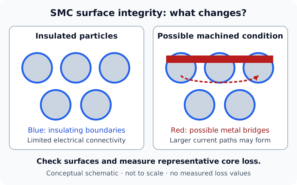
As an engineering mechanism, cutting or rubbing can deform exposed metal across adjacent particle boundaries. If those bridges connect into loops, alternating magnetic flux can drive currents over distances larger than an isolated particle. Surface particle smearing therefore deserves investigation even when the part meets its drawing dimensions. A smooth or reflective face alone cannot establish good magnetic performance.
Total core loss includes hysteresis and dynamic contributions. Machining can introduce local stress as well as alter electrical continuity, so a change in measured loss cannot automatically be assigned entirely to surface eddy currents. Likewise, bulk electrical resistivity and surface resistance are different measurements: a bulk datasheet value does not prove that a finished air-gap face is free of conductive bridges.
For simple sinusoidal models, classical eddy loss generally grows strongly with frequency and flux density; real SMC behavior also depends on particle distribution, geometry and excitation. Use that trend to choose a qualification matrix, not to calculate a universal machining penalty. No percentage increase, temperature rise or loss-recovery guarantee is established by this guide.
3. The Axial Flux Eddy Current Trap
An axial flux tooth presents a broad face toward the air gap. Where alternating flux crosses that face, a connected conductive surface can support circulating currents in the plane of the face. The concern is the combination of flux direction, conductive connectivity and loop dimensions. It does not establish that every axial motor is more vulnerable than every radial motor.
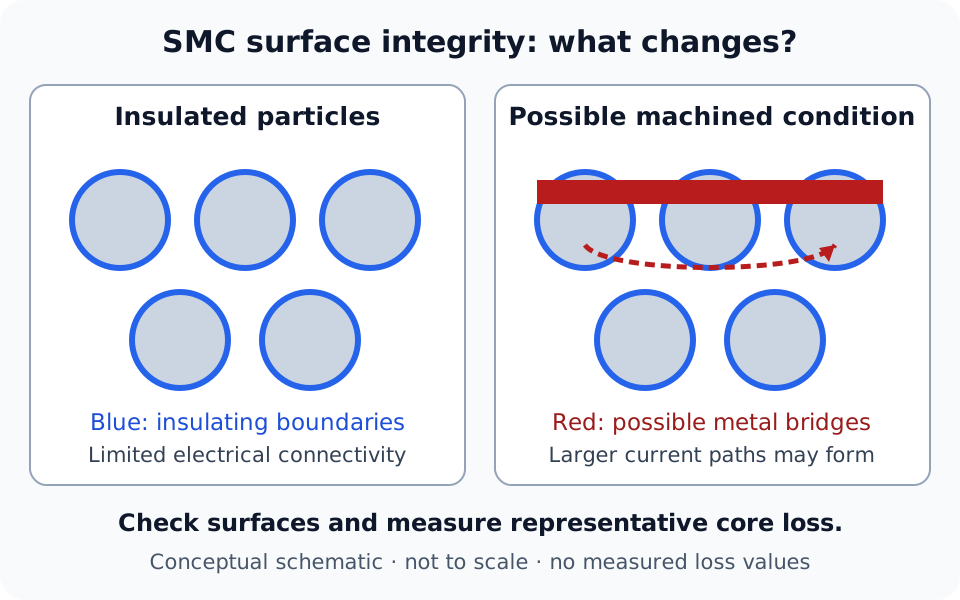
Figure 1: Conceptual schematic, not a micrograph or measured cross-section. Blue boundaries represent particle insulation; the red region illustrates possible machining-induced connections. Sizes, bridge continuity and loss magnitude are not to scale. The surface condition must be established on actual parts.
Use electrical frequency, rather than shaft speed alone, when specifying the test. For a synchronous permanent-magnet motor:
Fundamental electrical frequency (Hz) = pole pairs × speed (rpm) / 60
Example: 8 pole pairs × 6,000 rpm / 60 = 800 Hz
This is an arithmetic example, not a validated operating point. Inverter switching harmonics, local flux concentrations and nonsinusoidal operation may add losses beyond a sinusoidal material test. A low-frequency coupon result cannot by itself qualify the stator at its maximum speed.
If a prototype runs hotter than predicted, inspect the machined faces alongside waveform assumptions, density, winding loss, assembly shorts and cooling interfaces. Do not diagnose smearing from temperature alone. Retain an untreated reference and compare controlled process variants so that a proposed remedy can be distinguished from measurement scatter or a change in cooling.
4. Comparing SMC Prototyping and Production Routes
The comparison below is a purchasing framework. It deliberately leaves prices, lead times and tolerances to drawing-specific quotations. Net-shape parts may still require secondary finishing; a prototype die does not necessarily reproduce a production die's density distribution.
| Evaluation parameter | CNC machining from an SMC blank | Wire EDM, if feasible for the grade | Prototype compaction tool | Serial compaction tool |
|---|---|---|---|---|
| Geometry iteration | Toolpaths and fixtures can change | Profile changes may be practical | Tool changes may be needed | Tool changes need formal review |
| Upfront spending | Blanks, programming and workholding | Setup, wire and workholding | Die design and qualification | Die system and production qualification |
| Material traceability | Identify parent blank and treatment | Identify parent blank and treatment | Record powder lot and press settings | Control powder, pressing and furnace lots |
| Surface concern | Smearing, burrs, stress and cracks | Conductivity feasibility and thermally affected surface | Ejection damage and any secondary cuts | Tool wear, ejection damage and secondary cuts |
| Dimensional control | Inspect after all finishing | Inspect after final surface treatment | Validate springback and ejection | Establish capability on critical features |
| Magnetic evidence | Test the actual machining route | Test the actual EDM route | Measure representative compacts | Validate serial process and changes |
| Density representation | Blank may differ from a pressed tooth | Blank may differ from a pressed tooth | Map density on the prototype design | Confirm production density consistency |
| Suitable purchase objective | Geometry trials; qualified magnetic trials | Selected features after feasibility review | Bridging design to production | Repeatable supply of a stable design |
Wire electrical discharge machining (WEDM) needs particular caution. Insulating particle boundaries can affect electrical machining behavior. Where EDM is feasible, thermal damage or a recast layer becomes a separate qualification question. Do not accept either “no cutting force means no magnetic damage” or “an acid dip always fixes EDM” without process-specific evidence.
For compaction, ask whether the proposed shape can be filled, pressed and ejected without unacceptable density gradients, cracks or unsupported tool features. The compaction tooling DFM guide provides a starting point for that drawing discussion.
5. Machining Guidelines: Specify a Qualified Process Window
A generic feed-and-speed table cannot qualify every SMC grade, blank condition and tooth geometry. Höganäs' machining service overview discusses assessment and optimization for powder-metallurgy components. Its examples concern PM materials generally; they are not an SMC stator cutting specification or evidence of loss recovery.
For the actual blank, request the material manufacturer's current machining recommendations and the machining supplier's trial plan. Record cutter material, edge geometry, wear limit, cutting speed, feed, engagement and workholding. The goal is to limit rubbing and damage while supporting fragile features. Do not mandate PCD for every iron-based grade: the cutter must be suitable for the work material and verified in the intended operation.
Treat coolant compatibility as a material-specific decision. A blanket dry-cutting requirement is not justified for all SMC products, and using a fluid without compatibility evidence is also inadequate. Agree the cutting fluid or dry process, cleaning sequence, residual-contamination checks and corrosion controls before machining the qualification batch.
Air-gap faces, thin shoes and winding edges deserve separate inspection points. Include before-and-after dimensions if any secondary treatment removes material. A part can retain an acceptable overall length while losing local flatness or changing an edge that controls winding clearance. Preserve representative samples near the agreed tool-wear limit, rather than qualifying only the first part from a new cutter.
6. Chemical Etching: A Candidate Treatment, Not a Universal SOP
Chemical etching may be investigated to remove conductive surface bridges without further mechanical rubbing. It can also attack the particle insulation, enlarge pores, change dimensions or leave residues. The sources below do not establish a transferable acid concentration, immersion time, removal depth or thermal cycle that restores every SMC grade.
Do not release an acid-treatment recipe from this article. Ask the powder manufacturer and process supplier whether the proposed treatment is compatible with the named grade and its existing heat treatment. If the supplier cannot demonstrate compatibility and repeatable magnetic results, the treated prototype remains unqualified for electromagnetic conclusions.
A useful qualification request has five stages:
- Baseline: Identify blank lot, grade, prior treatment, dimensions and untreated reference samples. Photograph and map the surfaces of interest.
- Controlled trial: Have the qualified process owner define the chemistry, concentration control, temperature, duration and bath condition. Include an untreated control and trace each specimen.
- Cleaning and drying: Document a compatible removal, rinse and drying sequence. Check for retained liquid, residue and corrosion in porous features.
- Dimensional and material review: Measure critical faces after treatment and check for cracks, unacceptable edge attack or loss of handling strength.
- Magnetic release: Compare loss under matched test conditions and document whether the improvement is repeatable within measurement uncertainty.
Any additional bake requires grade-specific approval. “Stress relief” is not permission to heat an insulated powder compact using a cycle borrowed from steel laminations. A treatment that reduces mechanical stress can still damage the insulation system.
Before paying for a whole treated batch, discuss the proposed process and acceptance evidence. Include the supplier's compatibility statement and planned measurements so the review can address a defined decision.
7. Electromagnetic Testing: What Evidence Can Release a Prototype?
IEC 60404-6:2018 covers ring-specimen measurement of AC magnetic properties for relevant soft magnetic materials over 20 Hz to 100 kHz. The catalogue also identifies its 2021 amendment. Agree the applicable edition and laboratory method when placing the order. The standard describes measurement; it does not provide a universal machining acceptance limit or certify an etching process.
A ring specimen can help compare material and processing variants, provided its grade, density, thermal history and surface preparation are representative. A ring machined from the same blank is useful for traceability, but its flux direction and surface-to-volume ratio differ from a finished tooth. Ring results should support, rather than replace, validation of the intended stator assembly.
For surface electrical checks, agree probe geometry, contact force, locations, curvature corrections and conditioning. Porous, discontinuous conducting paths do not necessarily behave like a uniform thin film. A four-point measurement can be a comparative process indicator; an arbitrary sheet-resistance threshold is not a substitute for measured core loss.
Proposed test-record matrix
This table specifies evidence to request. It contains no measured results or promised recovery percentages.
| Record | Untreated reference | Machined condition | Candidate finished condition | Interpretation boundary |
|---|---|---|---|---|
| Grade and lot | Identify source | Match parent material | Retain traceability | Trade name alone is insufficient |
| Density and geometry | Record method and dimensions | Record removed surfaces | Record final dimensions | Density differences can confound loss |
| Microscopy | Map reference surface | Inspect bridges and damage | Inspect remaining damage | Appearance does not quantify loss |
| Surface electrical check | Record fixture and locations | Repeat at mapped locations | Repeat after conditioning | Compare like geometry and contacts |
| AC core loss | Record frequency, flux and waveform | Repeat matched conditions | Repeat matched conditions | Include uncertainty and temperature |
| Dimensional inspection | Record datum scheme | Record critical faces | Measure after all treatment | Treatment can change air-gap geometry |
| Assembly validation | Identify reference build | Record thermal and loss behavior | Repeat relevant operating points | Coupons cannot establish whole-motor efficiency |
Set release limits from the motor's loss budget and a demonstrated measurement method before testing. Report absolute loss in the appropriate units, specimen mass, temperature, excitation and uncertainty. Avoid turning a ratio to a different catalogue specimen into a claim that the motor has recovered the same efficiency.
8. Sourcing Economics: Calculate the Crossover for Your Quotes
Compare the cost of accepted parts at the same drawing revision and release standard. The following model assumes constant unit costs and one setup per route:
C_machined(N) = F_m + N × v_m
C_compacted(N) = F_c + N × v_c
N_break_even = (F_c − F_m) / (v_m − v_c)
Here, N is the number of accepted teeth. Fixed costs F include setup, dedicated tooling and fixed qualification work. Variable costs v include the quoted operations and per-part inspection. The crossover exists in this form only when machining has the higher variable cost; minimum orders and stepped pricing require a different calculation.
Hypothetical USD example — not market prices or a quotation
Assume machining setup F_m = $1,000, machining variable cost v_m = $450, compaction setup and tooling F_c = $12,000, and compaction variable cost v_c = $80. Assume both routes meet the same acceptance criteria, with no design revisions. The example excludes freight, duties, taxes, financing and additional motor validation.
| Accepted teeth | Machined route total | Compacted route total | Lower modeled cost |
|---|---|---|---|
| 5 | $3,250 | $12,400 | Machining |
| 10 | $5,500 | $12,800 | Machining |
| 20 | $10,000 | $13,600 | Machining |
| 30 | $14,500 | $14,400 | Compaction, by $100 |
| 50 | $23,500 | $16,000 | Compaction |
| 100 | $46,000 | $20,000 | Compaction |
The calculated crossover is 11,000 / 370 = 29.73, so compaction becomes less expensive at 30 accepted teeth under these assumptions. The $100 difference at that quantity is too small to ignore an omitted setup or inspection charge. This result is an arithmetic illustration, not a recommended universal purchasing threshold.
If a geometry revision adds $4,000 to the compaction route alone, its fixed cost becomes $16,000 and the crossover becomes 15,000 / 370 = 40.54, or 41 accepted teeth. If either route needs extra qualification, add that cost explicitly. With yield y, estimate starts as accepted quantity divided by y, subject to batch rounding and the supplier's actual scrap terms.
Request quote validity, currency, delivery terms, blank availability, tooling ownership, maintenance and revision charges. Compare delivery from drawing approval through final inspection, not only cutting time against die manufacture. The commercially cheaper route is usable only when its technical qualification and schedule fit the program.
9. Ten-Point B2B Procurement and SQE Checklist
Use these items in the RFQ and statement of work. Numerical limits should come from the drawing, material instruction and agreed validation plan.
- Material identity: Name the SMC grade, powder or blank lot, compaction history and approved heat treatment; request the applicable datasheet.
- Sample purpose: Identify geometry-only samples, magnetic validation parts and production approval parts separately.
- Route disclosure: Require the supplier to identify pressed surfaces, machined surfaces, EDM operations and any secondary treatment.
- Machining controls: Agree cutting tools, wear limits, workholding, compatible coolant or dry cutting, and cleaning records.
- Treatment qualification: Obtain grade compatibility and controlled trial evidence before authorizing chemical etching or an additional bake.
- Critical dimensions: Inspect air-gap faces, flatness, winding clearances and retention features after all finishing.
- Magnetic acceptance: Define frequencies, peak flux, waveform, temperature, loss limits, specimen representation and uncertainty.
- Lot sampling: Agree sample quantities, locations, retained controls and the evidence required after process changes.
- Preservation: Specify packaging and corrosion controls compatible with storage, bonding, potting and winding operations.
- Commercial terms: State accepted quantities, teeth per stator, tooling ownership, maintenance, revision charges and responsibility for rejects.
Review the manufacturing and quality information when aligning supplier records with incoming inspection. A certificate should identify the tested lot and method; a generic “SMC compliant” statement does not resolve a missing release criterion.
10. Frequently Asked Questions
Can we polish or sand a machined SMC surface to remove smearing?
Do not assume that a smoother surface is electrically better. Abrasion may remove damaged material, create new bridges or change critical dimensions. Qualify the proposed finishing operation with surface inspection and matched magnetic tests. Chemical treatment is also a candidate process requiring evidence, rather than the only acceptable remedy.
Does wire EDM eliminate the eddy current risk?
No route should receive that assumption. First confirm that EDM is practical for the selected grade. Then evaluate any thermally affected surface and its magnetic consequences. Avoid specifying a universal recast thickness or mandatory acid dip without supplier data for the actual operation.
Can chemical etching change the motor air gap?
Yes. Material removal, edge rounding and nonuniform attack can alter the finished geometry. Establish the allowance from trials, measure final faces against the drawing datums and include the change in the assembly tolerance stack. A generic immersion time cannot establish a dimensional offset.
Can we machine in the green state before final heat treatment?
Consider it only as a separately qualified route. Handling strength, fixture loads, edge damage and subsequent dimensional change must be checked for that material. General PM green-machining experience does not establish that an SMC tooth will survive handling or retain its required magnetic properties.
When should we switch from machining to compaction tooling?
When a sufficiently stable design, a qualified pressing route and comparable quotations justify it. Use accepted-part quantities and include qualification and revision risk. The worked crossover above demonstrates the calculation; it cannot establish a supplier price or a minimum economic order for your geometry.
What maximum frequency is safe for a machined and treated SMC stator?
There is no single frequency rating for the route. Evaluate the selected grade, flux density, waveform, geometry, cooling and total motor loss budget. A material's test-frequency range does not establish efficient or thermally acceptable motor operation throughout that range.
Does an epoxy or parylene coating solve conductive surface bridges?
External dielectric coating may help insulate the core from windings, but it does not necessarily interrupt existing metal connections beneath it. Distinguish winding-to-core insulation testing from core-loss qualification. Both functions need evidence appropriate to the finished assembly.
11. Sources and Reference Limits
Sources checked on November 7, 2026. These primary sources support material architecture, general process-development context and measurement scope. They do not supply this article's hypothetical prices, prove a universal smearing penalty or validate a chemical restoration recipe.
- Höganäs — Soft magnetic materials. Manufacturer overview of insulated iron particles, three-dimensional magnetic design and net shaping. It is not a comparative test of machined and pressed stator teeth.
- Höganäs — Machining. General PM machining assessment and process optimization. Its broader PM examples must not be treated as SMC-specific cutting or chemical-treatment instructions.
- IEC — IEC 60404-6:2018 catalogue record. Ring-specimen AC magnetic measurement scope; the record also lists the 2021 amendment. Obtain the applicable full standard for laboratory work. It does not prescribe the loss limit for your stator.
The route comparison, proposed test matrix, RFQ checklist and cost sensitivity calculation are this guide's engineering synthesis. They make the sourcing decision reproducible without presenting an illustrative model as a customer case study or measured hardware result.
12. Next Steps: Define the Prototype Decision Before Ordering
For a drawing review, prepare a STEP model and dimensioned drawing, SMC grade or candidate grades, teeth per stator, required accepted quantity, critical air-gap surfaces, operating frequencies and the proposed release tests. State whether the immediate objective is winding fit, magnetic validation or a production-representative build.
Send your stator RFQ for a drawing-led review to discuss route feasibility and the evidence needed before release. Use the SMC technology and materials overview to frame material questions and the compaction tooling DFM guide to identify features needing press and ejection review. Confirm price, lead time and any treatment capability in the resulting quotation and qualification plan.
Article-to-RFQ Workflow
Turn this guide into an evidence-ready RFQ.
Use the article context as the starting point, then align CAD status, magnetic targets, validation scope, and release records before asking suppliers to quote.
Capture the decision
Identify the topology, product family, operating point, and current gate before the article takeaway becomes a supplier question.
Attach buyer inputs
Prepare drawing status, magnetic targets, quantity plan, destination, and open risks in the RFQ worksheet.
Request evidence
Ask for DFM notes, first article inspection, magnetic validation, traceability, and packaging release files before price comparison.
Author

Categories
More Posts
CRGO Tape-Wound Cut Cores vs. Segmented SMC for Axial Flux Stators: Magnetic Anisotropy, Slitting Stresses, and Sourcing Economics
Compare CRGO tape-wound vs SMC axial flux stators: flux direction, cutting risks, grade-specific processing and tooling payback. Prepare a comparable core RFQ.
Axial Flux Motor Air Gap Tolerances and Unbalanced Magnetic Pull (UMP): Stator Core Flatness, Bearing Fatigue, and Sourcing Controls
Review axial flux air gap tolerances, UMP sensitivity, stator flatness and bearing fatigue. Use the sourcing checklist to prepare a drawing-led engineering RFQ.
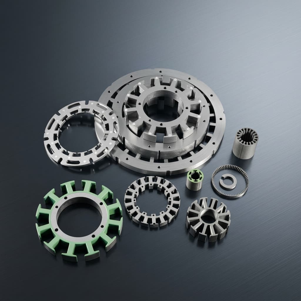
SMC vs. Laminated Steel for Axial Flux Motor Cores: A Procurement & Engineering Guide
An in-depth guide for procurement teams and engineers evaluating Soft Magnetic Composites (SMC) against laminated steel for axial flux motor cores.