
CRGO Tape-Wound Cut Cores vs. Segmented SMC for Axial Flux Stators: Magnetic Anisotropy, Slitting Stresses, and Sourcing Economics
Compare CRGO tape-wound vs SMC axial flux stators: flux direction, cutting risks, grade-specific processing and tooling payback. Prepare a comparable core RFQ.
Decision-level summary: Choose between CRGO tape-wound cut cores and segmented SMC axial flux stators using the actual flux path, finished-part loss data and a comparable quotation. Grain-oriented steel can be attractive when flux follows its rolling direction and the cutting/bonding process is qualified. SMC enables multidirectional magnetic paths and near-net-shape teeth, but permeability, hysteresis loss, density, retention and tooling cost still need validation. Neither route has a universal frequency or annual-volume threshold at which it becomes the better choice.
Published and reviewed: October 25, 2026. Scope: Global, English-language engineering and procurement comparison. This guide addresses iron-core AFPM stator sourcing; it does not qualify an EV, eVTOL or other safety-critical motor. Its method is to compare published manufacturer process descriptions, identify the evidence needed for a like-for-like RFQ, and show a reproducible tooling-payback calculation. It presents no AxialFluxCore dyno measurements, customer results or market-price survey. Supplier process guidance supports manufacturing possibilities, not a guaranteed motor-performance ranking.
For a project already at RFQ stage, request a core-route review with the drawing revision, pole count, speed/duty map and quantity plan. Use the compaction tooling DFM guide, manufacturing quality controls and magnetic loss validation requirements to define acceptance evidence.
1. The Core Architecture Dilemma in Axial Flux Stators
In an axial flux motor, flux crosses the rotor-stator air gap axially, but its path within the core depends on the topology. A yokeless segmented armature does not have the same stator back-iron path as a yoked annular design. Material selection therefore starts with the magnetic circuit and the way the core is assembled.
The CRGO tape-wound route forms a core from grain-oriented electrical steel strip and creates slots or cut faces using a qualified process. Bonding, clamping, cutting, insulation repair and any heat treatment must be considered together. Alternative electrical-steel architectures include punched and bonded segments; tape winding is not the only way to make a laminated axial flux stator.
The segmented SMC route compacts insulated iron powder into individual teeth, followed by grade-specific heat treatment and assembly. Tooling must accommodate powder filling, density distribution, punch movement and ejection. A CAD shape is not automatically pressable.
SWD's axial-flux production overview describes wound cores with machined or punched grooves and shaped laminated segments. This is evidence that steel routes can be industrialized, rather than being limited to a few prototypes. Höganäs' soft-magnetic materials overview explains particle insulation and three-dimensional magnetic-circuit design for SMC.
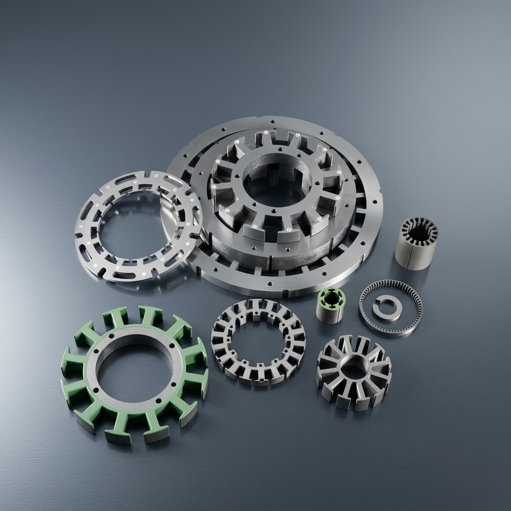
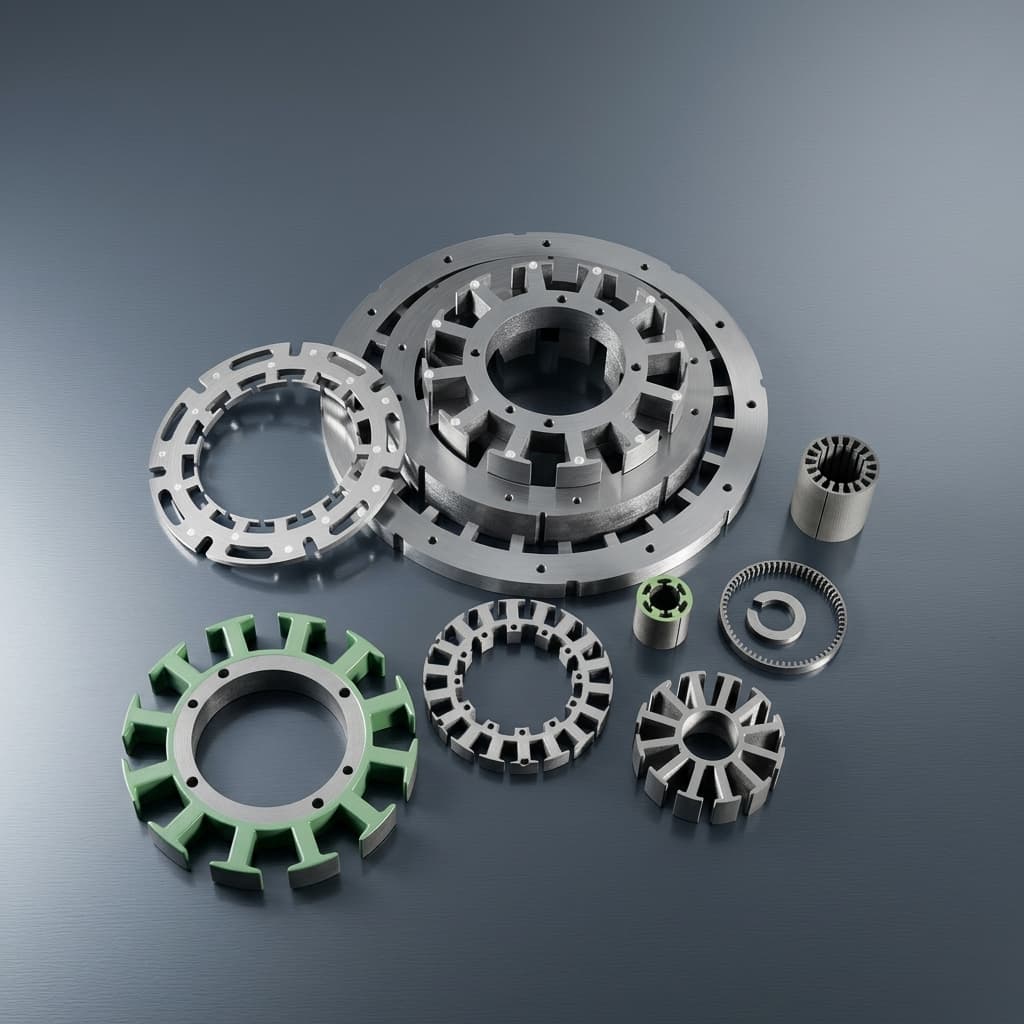
Illustrative product rendering, not a photograph of a tested CRGO/SMC comparison or a certified production part.
2. Electromagnetic Physics: Anisotropy vs. 3D Isotropy
2.1 Magnetic Anisotropy in Grain-Oriented Steel
CRGO's preferred magnetization direction is the strip rolling direction (RD). Transverse in-plane behavior and behavior normal to the sheet differ from RD and from each other. Permeability also varies with field strength; a single relative-permeability number cannot describe the whole motor operating range.
Do not assume that tape winding aligns RD with axial tooth flux. In a conventionally wound annulus, strip length follows the circumference. The supplier must mark RD, the transverse direction (TD) and the sheet normal on the actual winding/cutting drawing. A favorable RD catalogue curve is not transferable to a tooth whose dominant flux travels in TD.
Separate two risks: off-RD magnetization changes the magnetic response, while flux normal to a lamination can induce eddy-current paths governed by the in-plane dimensions. Magnetic flux does not itself puncture the insulation. Machining burrs or smearing can electrically bridge layers and create an additional loss mechanism. Use a 3D field model and finished-core measurements to determine whether either effect is material to the design.
2.2 Multidirectional Flux in Soft Magnetic Composites
SMC is commonly treated as approximately magnetically isotropic because it uses insulated powder particles rather than a continuous rolled sheet. This gives more freedom to shape a multidirectional magnetic path. It does not establish identical magnetic or thermal properties in every direction of every compacted component.
The approved powder grade, compaction density, heat treatment and particle insulation determine the usable B-H and loss curves. Particle insulation limits larger eddy-current paths, but coating damage and machining can reduce that benefit. Compare B at the same stated H, temperature and processing condition; do not relabel a catalogue induction point as universal saturation flux density or infer a motor-size reduction from it.
Conceptual comparison only: arrows illustrate inspection questions, not an RD-aligned winding layout, measured loss map or proof that either route runs cooler.
3. Manufacturing Risks of CRGO Tape-Wound Cut Cores
3.1 Slitting Stress and the Cut-Edge Effect
Slitting and subsequent slot cutting can introduce residual stress and a magnetically affected edge region. The extent depends on steel grade, thickness, cutting method, tool condition and tooth geometry. Wire EDM, milling and punching should not be assigned the same damage depth or loss penalty.
Ask for the process sequence and a comparison between representative material and the finished core. Record excitation, flux density, frequency, temperature and specimen geometry. Apply a measured process correction to the model; there is no justified blanket 30–70% loss multiplier for every CRGO tooth.
3.2 Cut Burrs and Interlaminar Short Circuits
Inspect cut faces for conductive bridges between wraps and define how insulation is restored or verified after machining. Request edge photographs, an agreed insulation test and finished-core loss data. SWD describes post-treatment to address machining-related shorts; their presence is a process-control question, not an inevitable failure of every wound core.
3.3 Stress Relief, Bonding and Flatness
Confirm whether stress-relief annealing is required for the selected steel and cutting route. Use the steel/coating supplier's approved temperature, atmosphere, time and handling sequence. Do not place an already resin-bonded assembly through a high-temperature process without establishing resin and coating compatibility.
Specify air-gap-face flatness and runout after the final heat treatment, bonding and clamping operations. Include a drawing-defined measurement datum and inspection state. Neither an annealing temperature alone nor a generic distortion allowance establishes an acceptable motor air gap.
3.4 Material Utilization and Machining Expense
Request incoming strip mass, finished core mass, slot-removal mass, scrap credit, machine hours and rework yield. Slot count and geometry determine material removal. Wound-and-punched and wound-and-machined routes can have different economics; neither a universal scrap rate nor a fixed machining price is transferable across suppliers.
4. The Segmented SMC Manufacturing Reality
4.1 Grade-Specific Compaction and Heat Treatment
The sequence is powder preparation, die filling, compaction, ejection, grade-specific heat treatment and inspection. The Höganäs Somaloy performance-level guide lists 600–800 MPa compaction for several grades, but different thermal routes: its detailed 3P entry describes two-stage air/steam treatment up to 530°C, while 5P specifies nitrogen treatment up to 650°C. These are supplier examples, not interchangeable furnace recipes or a process specification for every SMC tooth. Obtain the current grade-specific processing instruction before releasing tooling.
4.2 Benefits and Qualification Limits
- Near-net shape: Compaction can reduce slot-machining waste. Include powder handling losses, rejected compacts, secondary finishing and tool wear in the quotation.
- Tooth-shoe geometry: Contoured shoes may be feasible, subject to punch access, density and ejection. Shaped laminated steel segments are also possible; SMC does not have an exclusive claim to 3D teeth.
- Segmented winding: Open access to an individual tooth may help pre-wound-coil assembly. Copper fill depends on coil geometry, wire, insulation and insertion clearances, not solely on SMC versus steel.
- Mechanical and thermal limits: Check density gradients, cracks, retention loads, coolant compatibility and thermal interfaces. Magnetic isotropy does not prove thermal isotropy, fatigue life or adequate strength for an aerospace application.
5. Engineering & Procurement Comparison Matrix
Use this matrix to request evidence for the same motor duty and assembly boundary. It is a qualification framework, not measured supplier performance.
| Evaluation parameter | CRGO tape-wound cut cores | Segmented SMC stator teeth | RFQ evidence / acceptance question |
|---|---|---|---|
| Magnetic direction | RD, TD and sheet-normal responses differ | Approximately isotropic model may be usable | Mark directions; provide processed-material B-H data |
| Induction and permeability | Grade, direction and H determine usable B | Grade, density and H determine usable B | Compare at equal H and temperature, including local peak B |
| Core loss | Cutting, thickness, waveform and flux direction matter | Hysteresis, particle insulation and density matter | Request loss curves across the actual duty map |
| Cut-edge condition | Slotting may introduce stress and layer bridges | Net shaping avoids slot cutting; finishing can still damage surfaces | Inspect final faces and test after secondary operations |
| Thermal processing | Qualify steel, coating, bonding and annealing sequence | Use the selected powder grade's heat-treatment route | Identify recipe revision and final inspection stage |
| Air-gap-face geometry | Inspect after bonding, heat treatment and clamping | Inspect after heat treatment, finishing and assembly | Agree flatness/runout datums and measurement temperature |
| Material utilization | Depends on slot geometry and production route | Near-net shaping can reduce removal; rejects still count | State mass balance, accepted yield and scrap credit |
| Tooth shoes and winding | Wound or shaped laminated designs are possible | Pressable contours can support segmented assembly | Review geometry and coil clearance before tooling |
| Strength and retention | Bonding and clamping need load validation | Brittle compact and retention system need load validation | Test assembly loads, vibration and thermal cycling |
| Tooling investment | Fixtures and cutting/punching tools are route-specific | Die set, punches, trials and maintenance affect NRE | Separate tooling ownership, life and replacement cost |
| Cost and production capacity | Quote accepted complete core sets | Quote teeth per set, assembly and accepted complete sets | Compare at identical annual quantity and delivery terms |
For a geometry-specific trade-off, request a compaction tooling DFM review before treating a quoted powder grade as a finished tooth specification.
6. Operating Frequency: Why There Is No Universal Crossover
For a synchronous motor, electrical fundamental frequency is f_e = RPM × number of poles / 120. Here, poles means total magnetic poles, not pole pairs. A 16-pole motor at 6,000 RPM has a fundamental frequency of 800 Hz. This arithmetic says nothing by itself about which finished core has lower loss.
A useful comparison includes fundamental frequency, local flux-density vectors, temperature, waveform harmonics and the actual processed material. Higher electrical resistivity can reduce eddy-current losses, but SMC hysteresis loss and the steel's thickness, direction and processing condition can change the result. There is no defensible general rule that SMC wins above 400, 500 or 600 Hz.
Compare both routes at the required torque-speed points and cooling conditions. Use 3D FEA where flux direction changes significantly, then correlate the model with core-loss and motor tests. Evaluate copper loss, magnet loss, mechanical losses and thermal limits separately before claiming higher complete-motor efficiency.
7. Total Cost of Ownership and Sourcing Economics
Compare one accepted complete stator core set, stating whether coils, retention hardware and assembly are included. A per-tooth SMC price cannot be compared directly with a complete wound ring. For global sourcing, align currency, quotation validity, Incoterm, freight, duties and destination inspection.
Use C = F / Q + v, where F is one-time tooling/qualification cost, Q is the total number of accepted complete core sets over the chosen amortization period, and v is variable cost per accepted set. Normalize material, processing, assembly, inspection, yield and scrap credit into v; do not count the same rejection loss twice.
Illustrative Tooling Payback — Assumptions, Not Supplier Quotes
The following USD inputs are deliberately hypothetical. They demonstrate arithmetic only; they are not market prices, measured yields, an annual-volume recommendation or evidence that SMC is cheaper.
| Cost input / calculated result | CRGO route | SMC route |
|---|---|---|
| Assumed one-time tooling and qualification F | $8,000 | $32,000 |
| Assumed variable cost per accepted complete core set v | $42 | $30 |
| Tooling allocation per set at Q = 1,000 | $8 | $32 |
| Calculated total per set at Q = 1,000 | $50 | $62 |
| Tooling allocation per set at Q = 5,000 | $1.60 | $6.40 |
| Calculated total per set at Q = 5,000 | $43.60 | $36.40 |
Under these assumptions, break-even is (32,000 − 8,000) / (42 − 30) = 2,000 accepted sets, with both routes at $46 per set. If the assumed SMC variable cost is $36 instead, break-even moves to 4,000 sets. If its variable cost is at least the CRGO cost while its fixed cost remains higher, there is no volume-only payback in this model. Use committed lifetime volume, tooling life and replacement costs rather than assuming one year's forecast will be realized.
8. Procurement & Engineering Selection Checklist
Use this checklist to prepare a comparable RFQ and a release decision:
- Drawing and architecture: Identify topology, tooth/slot count, core-set boundary, datums and revision. Mark RD/TD/sheet normal for the CRGO candidate.
- Duty map: Provide pole count, continuous and peak RPM, torque, flux density, temperature, duty duration and inverter waveform assumptions.
- Processed-material evidence: Request B-H and loss data for the actual grade and process. Agree specimen geometry, excitation method and uncertainty; an Epstein strip test alone does not characterize a 3D SMC tooth or assembled stator.
- Cutting and insulation: For wound cores, document edge treatment and bonding sequence. For SMC, document any machining and how particle insulation is protected or requalified.
- Thermal route and dimensions: Record the grade-specific heat-treatment instruction. Require final flatness/runout results after the agreed assembly and clamping state.
- Density, strength and retention: Agree density and sampling criteria for the selected SMC grade, plus crack inspection and assembly load validation for both routes. Do not substitute a generic density minimum or TRS figure for a retention assessment.
- Commercial normalization: Quote accepted complete sets at prototype, pilot and serial quantities, including tooling ownership, service life, maintenance, lead time and delivery terms.
- Release gate: Complete representative core and motor tests against agreed loss, temperature, dimensional and mechanical criteria before production approval.
9. Frequently Asked Questions (FAQ)
Q1: Can a CRGO tape-wound core have the same tooth-shoe geometry as an SMC stator?
Not automatically, but laminated steel is not restricted to straight teeth. Wound cores with secondary processing and shaped bonded laminations provide different options. SMC offers additional shaping freedom only within the filling, compaction and ejection limits of its tooling. Compare manufacturable drawings, coil clearance and interfaces before choosing a route.
Q2: Is Somaloy mechanically strong enough for automotive or aerospace use?
A grade name alone cannot answer that. Use processed-part strength data and the actual retention design to assess electromagnetic loading, vibration, fatigue, thermal cycling and impact. Qualification and any application-specific approval require separate evidence; this guide provides neither.
Q3: What if a wound core's bonding varnish degrades?
Loss of bonding can allow lamination movement, noise and dimensional instability. The consequence depends on mechanical containment, operating temperature, coolant exposure and loading. Request resin-compatibility evidence and retained-core testing rather than assuming either guaranteed failure or guaranteed safety.
Q4: Can we machine an SMC blank before investing in compaction tooling?
It can be a prototype route if suitable blanks and a qualified machining process are available. Surface smearing, density and material condition can make a machined blank magnetically different from a production compact. Use it to answer defined geometry or assembly questions, then revalidate loss and strength on the intended serial process. See the SMC prototyping and DFM guide for tooling considerations; prototype results do not automatically qualify the production tooth.
Q5: Is SMC always better at carrying heat out of an axial flux stator?
No. Compare grade-specific thermal conductivity, direction, density, bonding, potting and the path to the coolant. Laminated cores can have directional thermal resistance, while SMC properties also depend on processing. A whole-stator thermal model and temperature measurements are needed to establish a cooling advantage.
10. Sources and Reference Limits
Manufacturer pages below were reviewed on October 25, 2026. They support the stated material/process possibilities. They do not establish comparative dyno results, universal loss penalties, aerospace qualification or the hypothetical costs above.
- SWD AG — Axial flux motor. Production overview covering wound/bonded or welded cores, machined or punched grooves, shaped laminated segments and post-treatment for machining-related shorts. Its industrialization examples do not prove one route is best for this reader's motor.
- Höganäs — Soft magnetic materials. Explains insulated iron particles, three-dimensional magnetic circuits and net shaping. This is supplier technology guidance, not an independent head-to-head motor test.
- Höganäs — Somaloy powders for electromagnetic applications. Lists performance levels and grade-dependent compaction/heat-treatment examples. Confirm the current powder-specific datasheet and processing instruction with the supplier; the overview is not a complete manufacturing specification.
11. Sourcing and Engineering Collaboration
Use SMC stator segments and YASA segmented teeth as starting points for geometry discussions. Agree the required magnetic loss validation evidence and manufacturing quality documentation before comparing offers.
To request a stator-core RFQ review, provide your drawing revision or non-confidential envelope, topology, pole count, speed/duty map, acceptance criteria, prototype quantity, lifetime volume and delivery destination. State the NDA and file-handoff requirements before sharing sensitive CAD. The next step is to agree which material/process candidates need samples and what evidence will decide between them.
Article-to-RFQ Workflow
Turn this guide into an evidence-ready RFQ.
Use the article context as the starting point, then align CAD status, magnetic targets, validation scope, and release records before asking suppliers to quote.
Capture the decision
Identify the topology, product family, operating point, and current gate before the article takeaway becomes a supplier question.
Attach buyer inputs
Prepare drawing status, magnetic targets, quantity plan, destination, and open risks in the RFQ worksheet.
Request evidence
Ask for DFM notes, first article inspection, magnetic validation, traceability, and packaging release files before price comparison.
Author

Categories
More Posts
Direct Needle Winding on Segmented SMC Axial Flux Teeth: Slot Fill Factors, Wire Tension Fracture Limits, Corner Radius DFM, and Sourcing Controls
Compare direct needle winding on SMC axial flux teeth: copper fill, tension trials, corner radii and insulation. Prepare your drawing-led RFQ for DFM review.
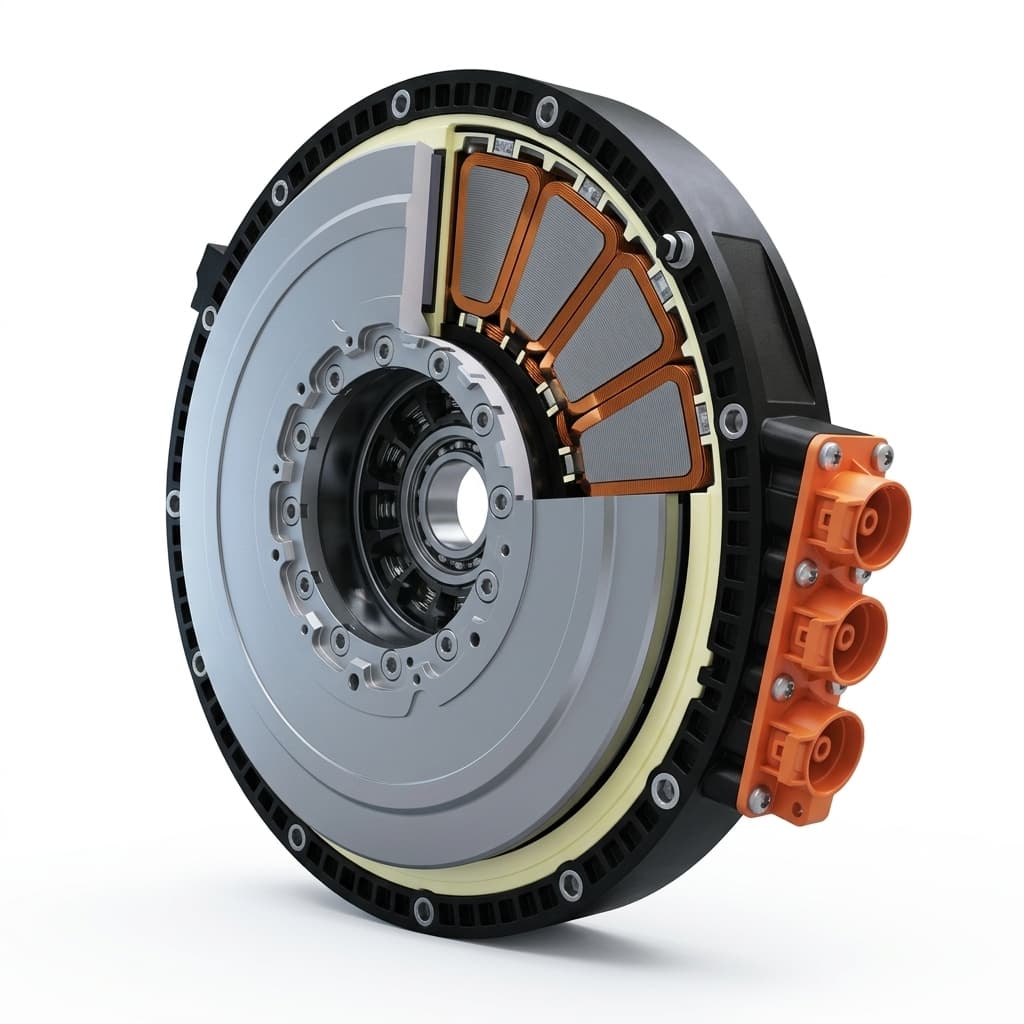
Mercedes-Benz Launches Large-Scale Axial Flux Motor Production: What It Means for the Supply Chain
Mercedes-Benz axial flux motor production in Berlin changes AFPM sourcing. See supplier tolerances, SMC stator risks, evidence gaps, and RFQ actions.
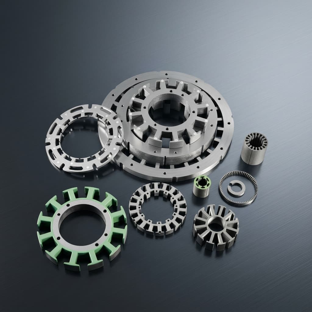
Thermal Management in Axial Flux Motors: Direct Oil Cooling and Stator Core Design
Engineering guide to axial flux motor thermal management, direct oil cooling, SMC stator design, validation risks, supplier evidence, and RFQ checks for buyers.