
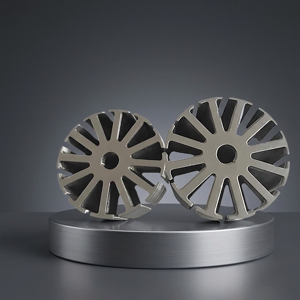
Axial Flux Motor Air Gap Tolerances and Unbalanced Magnetic Pull (UMP): Stator Core Flatness, Bearing Fatigue, and Sourcing Controls
Review axial flux air gap tolerances, UMP sensitivity, stator flatness and bearing fatigue. Use the sourcing checklist to prepare a drawing-led engineering RFQ.
Decision-level summary: Axial flux air gap tolerances must cover the assembled geometry, bearing displacement, temperature and rotor deflection. Stator flatness alone cannot establish minimum running clearance or bearing life. Allocate a gap budget, calculate force sensitivity for the actual magnetic circuit, and agree drawing datums and inspection evidence before ordering tooling. There is no universal safe air gap or SMC flatness value for every motor.
Published and reviewed: October 28, 2026. Scope: Global B2B engineering, procurement and supplier quality for iron-core axial flux permanent magnet (AFPM) motors. The worked force example concerns a symmetric two-gap assembly under a uniform axial offset. Single-sided machines, local stator tilt and rotor bending need different load models. This guide provides illustrative calculations and a sourcing framework; it contains no measured motor test results, certified supplier capability study or product lifetime guarantee.
Moving from simulation to prototype tooling? Request a drawing-led engineering review with the target gap, datum scheme, rotor support layout and operating envelope. The compaction tooling DFM guide and manufacturing quality controls help define the evidence package.
1. Air Gap Physics: Flatness, Magnetic Pull and Structural Stiffness
In an axial flux machine, magnetic pressure acts across the rotor and stator faces. An unequal gap can create an axial force imbalance; a nonuniform pressure distribution can also create a tilting moment. Radial flux machines can suffer damaging UMP too: neither topology has a generally safe percentage of eccentricity.
For a predominantly normal, approximately uniform gap field, the Maxwell-pressure estimate is:
Fz ≈ Bg² × A / (2μ0)
Here Bg is the assumed uniform normal flux density in tesla, A is total active face area in square metres, and μ0 = 4π × 10⁻⁷ H/m. A spatial peak field cannot simply be applied over the whole face. A detailed model integrates the normal and tangential field stress over the surface.
For an illustrative 16-pole face with 1,560 mm² active area per pole and uniform Bg = 1.00 T, A = 0.02496 m² gives approximately 9,931 N per face. Equal opposing forces can cancel the net axial resultant in a symmetric assembly; each rotor and its supports still carry substantial internal loads. Cancellation does not imply hydrostatic compression or zero disc bending.
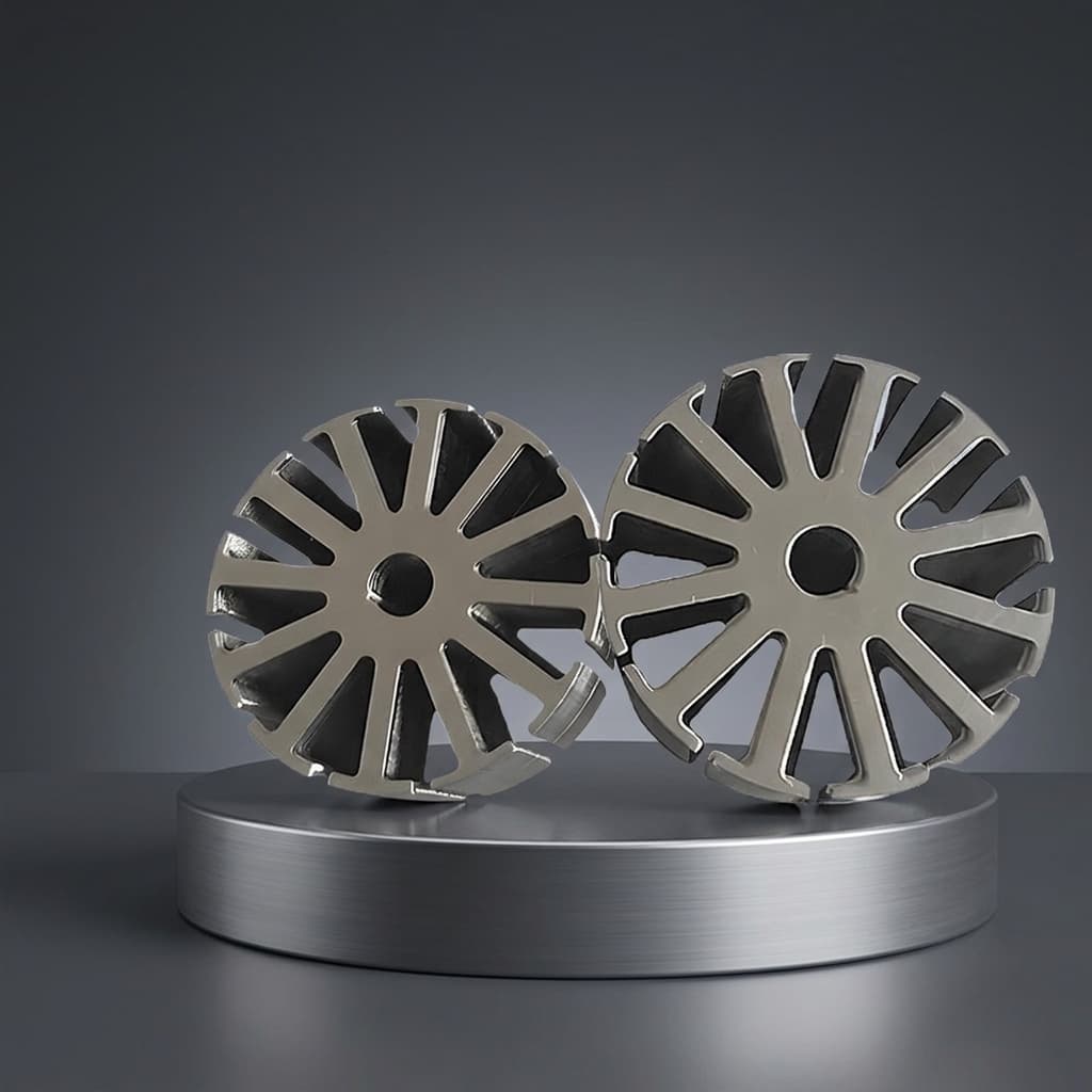
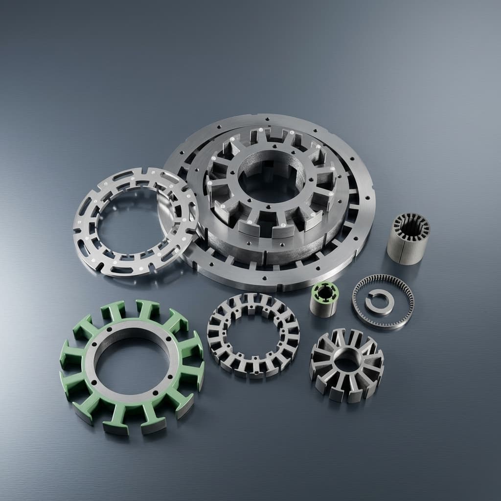
Figure 1: Product illustration of modular SMC stator geometry. The image does not document measured flatness, runout or machining capability.
If a closing gap raises attraction, the force can reinforce displacement. Define the destabilizing force slope as kmag = dFnet/dx. For a single linearized axial degree of freedom, local static stability requires kmech − kmag > 0. Rotor tilt, disc bending, bearing preload and dynamic resonance require a coupled model. A fixed 3× stiffness factor is not a general standard or a substitute for that analysis.
2. Reproducible UMP Sensitivity: An Illustrative Magnetic Circuit
A force law proportional to 1/g² assumes an air-gap-dominated circuit and fixed excitation; it is not a universal permanent-magnet motor law. To show the effect of magnet reluctance, use this deliberately simplified fixed-MMF circuit:
- Nominal gap on each side:
g0 = 0.80 mm. - Assumed magnet thickness:
lm = 4.00 mm; recoil relative permeability:μr = 1.05. - Baseline force per face:
F0 = 9,931 N, from the rounded estimate in Section 1. - Closing and opening gaps:
gclose = g0 − x,gopen = g0 + x. - Force on either side:
F(g) = F0 × [(lm + μr × g0) / (lm + μr × g)]². - Net force magnitude:
FUMP = F(gclose) − F(gopen).
Use millimetres consistently in the force ratio. The two faces are treated as identical independent circuits with uniform fields. Leakage, saturation, slotting, armature reaction and coupling through the shared magnetic path are omitted. The table is a reproducible screening example, not a 3D FEA result, test dataset or acceptance specification.
Figure 2: Conceptual section showing local gap nonuniformity. It is not to scale and does not depict the uniform-offset calculation below.
| Axial offset x (mm) | Closing gap (mm) | Opening gap (mm) | Closing-face force (N) | Opening-face force (N) | Net UMP (N) |
|---|---|---|---|---|---|
| 0.000 | 0.800 | 0.800 | 9,931 | 9,931 | 0 |
| 0.025 | 0.775 | 0.825 | 10,040 | 9,824 | 215 |
| 0.050 | 0.750 | 0.850 | 10,150 | 9,719 | 431 |
| 0.080 | 0.720 | 0.880 | 10,285 | 9,595 | 690 |
| 0.100 | 0.700 | 0.900 | 10,376 | 9,514 | 863 |
| 0.150 | 0.650 | 0.950 | 10,610 | 9,315 | 1,295 |
| 0.200 | 0.600 | 1.000 | 10,852 | 9,122 | 1,730 |
Table 1: Rounded arithmetic from the stated magnetic-circuit assumptions. Recalculate using the real geometry and validated material data before allocating loads.
At x = 0.100 mm, this model gives about 863 N, illustrating why a gap offset alone cannot determine UMP without a magnetic-circuit model. The small-offset slope is kmag = 4 × F0 × μr / (lm + μr × g0) ≈ 8.62 kN/mm. The figure is model-specific.
A uniform axial offset in an otherwise axisymmetric assembly does not establish a tilting moment. Calculate moment from the spatial pressure distribution, for example by integrating r × dF about the shaft reference. Multiplying the total axial force by mean pole radius would incorrectly assign an eccentric lever arm to a symmetric load.
3. The 6-Interface Tolerance Stack Budget
Track each contribution as a one-sided gap-closing displacement at the controlling radius and operating condition. Do not mix a bilateral height tolerance, a total profile zone and a peak-to-peak runout value without transforming them into the same clearance coordinate.
The numbers below are illustrative allocation inputs, not supplier capability claims or recommended production tolerances. The six rows are treated as nonoverlapping contributions; if assembled-face inspection already includes tooth and carrier errors, do not count those errors again.
| Interface | Gap-closing contribution | Example prototype allocation (mm) | Example series allocation (mm) | Evidence to request |
|---|---|---|---|---|
| 1. Tooth height | Tooth end-face position after final processing | 0.035 | 0.015 | Final-state height map, lot identity and gauge method |
| 2. Carrier and assembly | Mounting face, pocket depth and bond-line distortion | 0.040 | 0.020 | Datum-referenced map after bonding and bolting |
| 3. Rotor face | Hub, disc, magnet thickness and bond-line runout | 0.045 | 0.025 | Face displacement at inner and outer active radii |
| 4. Bearing support | Clearance, preload and load-dependent movement | 0.030 | 0.015 | Force-displacement curve over the temperature range |
| 5. Thermal state | Differential expansion and thermal bow | 0.040 | 0.025 | Thermal model with assembly reference temperature |
| 6. Operating deflection | Disc and support movement under speed and magnetic load | 0.050 | 0.030 | Coupled structural model and instrumented validation |
| Arithmetic closing sum | Sum of all six allocations | 0.240 | 0.130 | Preserve signs and avoid double counting |
| Remaining gap from 0.800 mm | Nominal gap minus arithmetic closing sum | 0.560 | 0.670 | Additional clearance reserve still requires approval |
Table 2: Example allocation worksheet. Neither remaining clearance is an approved safe operating gap.
For reference, the RSS of these inputs is 0.0992 mm for the prototype column and 0.0548 mm for the series column. These are mathematical combinations, not automatically 3σ predictions. RSS is meaningful for independent, centered random contributors expressed on a common statistical basis. Thermal growth and magnetic deflection are operating-state shifts; combine those deterministically with a justified manufacturing distribution instead of treating them as independent random errors.
The drawing owner should define a required positive clearance reserve for transients, measurement uncertainty and unmodeled effects. Compare the full assembly against that project requirement at cold start, hot steady state, maximum speed and agreed fault/load cases.
4. Laminated Steel vs. Segmented SMC: What Sourcing Must Verify
Laminated electrical steel and SMC offer different manufacturing routes. Neither material alone guarantees the finished stator's flatness. Choose on magnetic loss, flux path, mechanical strength, temperature and demonstrated final-state dimensional capability.
4.1 Laminated Stators
Sheet thickness, burr orientation, clamping, bonding and stress relief can affect stack height and face position. Ask for stack-height measurements under the specified clamping condition. Do not infer total stack error from an unsourced sheet-gauge percentage.
Machining exposed lamination edges can smear metal across interlaminar insulation. A proposed finishing route therefore needs insulation and core-loss qualification; it is not categorically impossible. Request before/after loss data at the intended frequency and flux density, together with burr and surface inspection.
4.2 SMC Stators
Höganäs describes SMC as electrically insulated iron powder formed into complex shapes by powder metallurgy. This supports three-dimensional flux paths and net shaping. It does not establish a universal tooth-height tolerance, cure temperature, density or grinding allowance.
For the selected grade and geometry, request the compaction direction, density distribution, heat-treatment route, ejection risk and final dimensional measurements. Secondary grinding can damage particle insulation or alter surface properties; qualify magnetic loss and insulation after the actual process. Do not accept a claim of “zero electrical shorting” based solely on the material being SMC.
Use the compaction tooling DFM review to identify which faces can be controlled in tooling and which need a qualified secondary operation before the tooling PO is released.
5. GD&T Matrix: Turning Gap Requirements into Inspectable Drawings
ASME Y14.5-2018 (R2024) defines the drawing language; it does not prescribe motor-specific tolerances. Select one governing GD&T system and have the drawing owner specify the numerical values. The following matrix describes control intent rather than ready-to-copy feature-control frames.
For an illustrative assembly, Datum A is the mounting plane, Datum B is the functional locating bore/axis, and Datum C clocks the assembly if required. Datum precedence and degrees of freedom must match the real locating features. A datum axis used for face runout must correspond to the functional shaft or inspection fixture axis.
| Feature | Control intent | Datum consideration | Inspection evidence | Sourcing decision |
|---|---|---|---|---|
| Mounting flange | Flatness | Form control has no datum reference | Surface map in stated free or restrained condition | Can the mount establish the intended plane? |
| Locating bore | Orientation and location | Relate bore axis to mounting plane and other functional locators | Bore measurements at multiple axial positions | Does the bore align the assembly as intended? |
| Individual tooth | Height or face location | Use the functional seating surface | Height distribution after final treatment | Can interchangeable teeth meet the allocation? |
| Individual pole face | Local flatness | Separate local form from face location | Surface sampling dense enough to detect local peaks | Are local gap pinch points controlled? |
| Tooth face to seat | Parallelism | Reference the tooth's defined seating datum | Face-to-seat orientation report | Does assembly introduce a wedge? |
| All assembled pole faces | Common surface profile requirement | Define basic geometry, shared zone and functional datum frame | Post-cure, post-clamp map of every active face | Is the complete face envelope controlled? |
| Face relative to shaft axis | Axial runout or equivalent displacement map | Use the actual functional rotation axis | Sweeps at inner and outer radii on an agreed fixture | Is rotor-facing displacement within the allocation? |
| Adjacent teeth | Relative face step | Define measurement locations and assembly condition | Neighbor-to-neighbor height differences | Will local steps escape a sparse inspection plan? |
Table 3: Drawing and metrology decision matrix. A stationary stator's runout inspection describes its geometry relative to an axis; it does not imply the stator rotates in service.
Specify fixture loading, bolt torque, temperature, sampling density, instrument uncertainty and reporting convention. Flatness alone controls form, not the face's position or orientation to the rotor. FAI or PPAP requirements must be agreed in the purchase specification; a GD&T note alone does not create a PPAP package.
6. Bearing Fatigue and Mechanical Stiffness
6.1 Convert Magnetic Loads into Bearing Loads
Use the magnetic model's forces and moments with the actual support geometry to calculate bearing reactions. For a catalogue bearing, equivalent dynamic load may use P = X × Fr + Y × Fa; the factors and applicability depend on bearing type, axial/radial load ratio and the manufacturer's rules. UMP cannot be converted directly into bearing life without those inputs.
For a constant-load ball-bearing example, the basic rating-life relation is L10h = [10⁶ / (60 × n)] × (C/P)³, where n is speed in rpm and C and P use the same load units. Roller bearings use a different exponent. At an assumed n = 6,000 rpm, changing P/C from 0.10 to 0.20 changes basic calculated life from approximately 2,778 hours to 347 hours, an eightfold reduction. This is load-sensitivity arithmetic, not a prediction for a named motor.
ISO 281:2007 defines basic rating life at 90% reliability under its stated assumptions. It excludes wear, corrosion and electrical erosion. Lubrication, contamination, preload, misalignment and a variable duty cycle require further bearing-manufacturer analysis. The example cannot determine a spalling time or prove service life.
6.2 Specify the Whole Support System
Obtain axial and tilting stiffness versus load, preload and temperature for the complete bearing/shaft/housing/rotor assembly. The series relation 1/kmech = 1/kdisc + 1/kshaft + 1/kbearing applies only to a simplified common axial load path. Real support systems can contain parallel paths and coupled modes.
Preloaded angular-contact pairs may provide useful axial and moment stiffness; four-point-contact or other bearings may suit different envelopes and load spectra. Check preload retention and thermal movement rather than declaring one arrangement mandatory. A radial clearance class such as C3 does not directly specify assembled axial float.
Hybrid ceramic bearings can be considered as part of an electrical-bearing-current strategy. Do not assume they eliminate every current path or increase whole-assembly stiffness by the same percentage as the ball material's elastic modulus. Selection requires manufacturer data and a system-level electrical and mechanical review.
7. Procurement and Quality Acceptance Checklist
Use this checklist with the engineering owner and supplier quality engineer before tooling release or first-article approval. Replace example numbers with controlled project requirements.
- Operating envelope: Record topology, speed, torque/load cases, temperatures and required noncontact clearance reserve.
- Gap budget: Assign all six contributors, distinguish state shifts from random variation and remove duplicate contributions.
- Drawing baseline: Approve revision, datums, geometric zones, restraint condition and active measurement radii.
- Material identity: Confirm electrical-steel or SMC grade, treatment and magnetic data at the intended operating conditions.
- Process capability: Obtain final-state dimensional samples and a gauge study; agree sampling, capability targets and handling of nonconforming parts.
- Finishing qualification: For any machined face, compare loss, insulation, burrs and geometry before and after finishing.
- Assembly stability: Map pole faces after bonding, potting and bolting, and repeat after a project-defined thermal cycle.
- Support validation: Review bearing reactions, preload, stiffness, disc deflection and bearing life across the duty cycle.
- Motor validation: Agree sensor placement, slow-roll clearance maps, hot/speed testing and abort thresholds before testing.
- Release evidence: Agree FAI/PPAP scope, lot traceability, inspection frequency and change/requalification triggers in the PO.
The manufacturing quality page outlines evidence planning. A requested 100% inspection plan or capability target becomes a supply commitment only when accepted for the specific part and order.
8. Frequently Asked Questions
How tight should axial flux motor air gap tolerances be?
Work backwards from the minimum permissible running clearance and electromagnetic sensitivity of the actual motor. Allocate geometry, bearing movement, thermal shifts and operating deflection separately. The 0.80 mm nominal gap and allocation values here are examples; they are not universal traction, robotics or drone recommendations.
Is stator flatness enough to prevent unbalanced magnetic pull?
No. A flat face can still be tilted or displaced relative to the rotor. Check assembled surface location and orientation, rotor runout, local tooth steps and load-dependent movement. A uniform axial offset and local tilt also produce different force and moment distributions.
Can grinding correct laminated or SMC stator faces?
Potentially, if the material grade, fixture, machining allowance and finishing process are qualified. Lamination-edge smearing and SMC particle-insulation damage are both concerns. Require post-process magnetic-loss and insulation evidence; geometry alone cannot establish magnetic acceptability.
How does temperature change the gap budget?
Use the assembly's locating scheme and temperature distribution. As an illustrative calculation, two 100 mm load paths with assumed expansion coefficients of 23 and 12 μm/(m·K), both heated by 100 K, differ in growth by 0.110 mm. That difference does not automatically equal gap closure: bearing locations, constraints and stator thermal bow determine the direction and magnitude. Use grade-specific data in the released model.
Can back-EMF or vibration measurements prove the motor has no UMP?
No. They can flag asymmetry but are not unique measurements of magnetic pull. Combine circumferential and radial clearance maps with calibrated displacement probes, support-load/deflection evidence and instrumented hot/speed testing. Probe target material and temperature affect calibration. Harmonic peaks depend on topology, winding, speed and fault type; there is no universal diagnostic frequency or 10% gap threshold that approves every motor.
9. Sources and Engineering References
- ASME — Y14.5-2018 (R2024), Dimensioning and Tolerancing. Publisher reference for GD&T terminology and interpretation. It does not prescribe the motor-specific tolerances in a supplier drawing.
- ISO — ISO 281:2007, Rolling bearings — Dynamic load ratings and rating life. Publisher scope for basic and modified rating life, including reliability assumptions and excluded failure mechanisms. The catalogue entry is not a substitute for the complete standard or bearing-specific calculation.
- Höganäs — Soft magnetic materials. Manufacturer explanation of insulated iron-powder SMC, net shaping and three-dimensional magnetic circuits. It does not substantiate a universal grinding precision or loss-free machining claim.
Evidence boundary: The formulas, worked examples, allocation worksheet and RFQ framework are editorial engineering analysis with explicit assumptions. None of these sources validates the example motor, reports our factory capability, or supplies a measured UMP dataset. Source scope reviewed October 28, 2026.
10. Engineering Review and Stator Sourcing Next Steps
A useful RFQ connects the drawing tolerance to the motor's clearance budget and a repeatable inspection method. Include the 2D/3D drawing revision, nominal gap, active radii, material grade, assembly restraints, operating envelope, volume and required validation records.
Send your stator drawing and gap budget for a DFM and quotation review. Ask which requirements can be supported in the as-pressed or assembled condition, which require secondary finishing, and which need sample qualification before a capability or inspection commitment can be made.
Use the compaction tooling DFM guide for tooling decisions and the manufacturing quality controls to agree the project-specific release evidence.
Article-to-RFQ Workflow
Turn this guide into an evidence-ready RFQ.
Use the article context as the starting point, then align CAD status, magnetic targets, validation scope, and release records before asking suppliers to quote.
Capture the decision
Identify the topology, product family, operating point, and current gate before the article takeaway becomes a supplier question.
Attach buyer inputs
Prepare drawing status, magnetic targets, quantity plan, destination, and open risks in the RFQ worksheet.
Request evidence
Ask for DFM notes, first article inspection, magnetic validation, traceability, and packaging release files before price comparison.
Author

Categories
More Posts
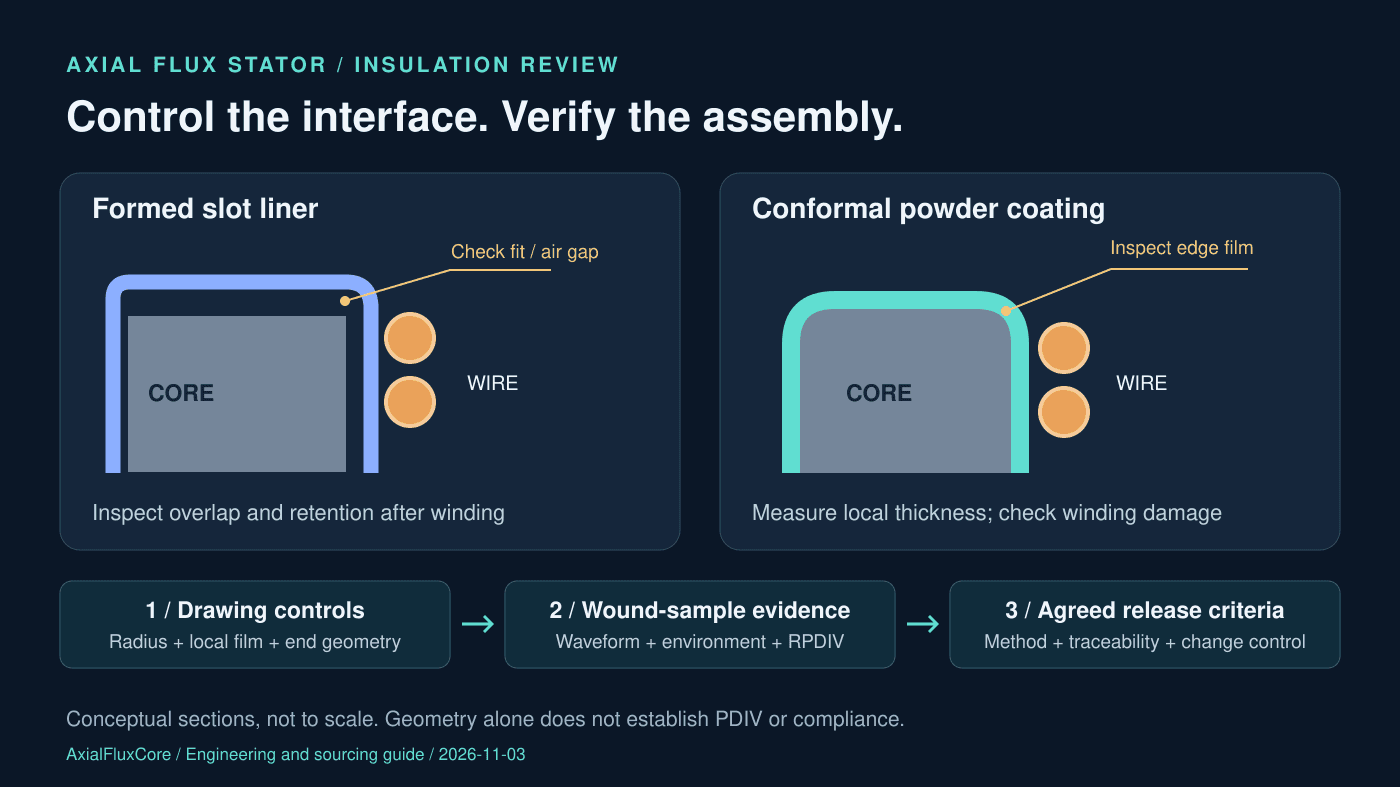
Axial Flux Stator Slot Insulation and PDIV in 800V SiC Systems: Epoxy Powder Coating vs. Slot Liners, Edge Radii, and Sourcing Controls
Compare axial flux stator slot insulation and PDIV for 800V SiC drives. Evaluate powder coating, liners and edge controls, then prepare your drawing-led RFQ.
Thermal Management in Axial Flux Motors: Direct Oil Cooling and Stator Core Design
Engineering guide to axial flux motor thermal management, direct oil cooling, SMC stator design, validation risks, supplier evidence, and RFQ checks for buyers.
Direct Needle Winding on Segmented SMC Axial Flux Teeth: Slot Fill Factors, Wire Tension Fracture Limits, Corner Radius DFM, and Sourcing Controls
Compare direct needle winding on SMC axial flux teeth: copper fill, tension trials, corner radii and insulation. Prepare your drawing-led RFQ for DFM review.