
Yokeless Axial Flux Stator Tooth Retention and Potting: Mechanical Interlocking, Resin Shear Fatigue, and Sourcing Controls
Review tooth retention, interlocking geometry, resin shear fatigue, and thermal shock in yokeless (YASA) axial flux stators. RFQ checklist and testing gates.
Decision-level summary: Yokeless axial flux stator tooth retention needs a defined load path from each tooth to the housing. Mechanical stops, clamshell pockets, bonding and potting can share that task, but room-temperature adhesive strength alone cannot establish retention over a motor duty cycle. For sourcing, request hot and aged joint data, a manufacturable retention drawing, and assembly tests tied to your torque, air-gap, temperature and coolant requirements. There is no universal push-out force, resin chemistry or allowable void percentage for every yokeless stator.
Published and reviewed: November 1, 2026. Scope: Global B2B engineering, procurement, and supplier quality assurance for iron-core Yokeless and Segmented Armature (YASA) axial flux permanent magnet (AFPM) machines. The screening calculations below assume a symmetric dual-rotor, single-stator layout. Single-rotor machines, unsegmented stators and ironless designs require different load models. This is a drawing and qualification framework, with no proprietary motor test data or claim of affiliation with YASA. Numerical examples are assumptions for reproducible screening, not measured material properties or release limits.
Preparing a prototype RFQ? Request a drawing-led engineering review with your tooth CAD, torque envelope, carrier datums and operating temperatures. The compaction tooling DFM guide, manufacturing quality controls, and AFPM SMC stator solutions identify related sourcing requirements.
1. Eliminating the Stator Yoke Shifts the Reaction Load Path
A continuous stator yoke can provide both a magnetic return path and a structural connection to the housing. Removing it changes how individual teeth are located and how their reaction forces reach the housing. Reduced yoke mass does not, by itself, establish a particular motor efficiency or torque density.
For each tooth, the structural model must include:
- Tangential force: Electromagnetic torque reaction through the tooth, carrier, joints and housing mounts.
- Axial force: Opposing rotor attractions may balance in an ideal symmetric assembly, but each side still carries local magnetic loading. Air-gap mismatch, rotor runout and operating transients can produce a net axial load.
- Tilting moment: The offset between the magnetic force resultant and the retention features creates bending and rotation that can consume running clearance.
1.1 Worked torque-to-force screening example
For equal load sharing, a first estimate is:
Ft = T_total / (r_effective × N_teeth)T_total is electromagnetic torque summed across both rotor faces; do not double-count it. r_effective is the force-weighted active radius, and N_teeth is the tooth count. The arithmetic mean radius is only a screening approximation; use electromagnetic force integration for final sizing.
Assume 450 N·m peak torque, 15 teeth, and inner/outer active radii of 85/125 mm. Taking r_effective ≈ (85 + 125) / 2 = 105 mm = 0.105 m:
- Assembly tangential force:
450 / 0.105 ≈ 4,286 N. - Equal-share force per tooth:
4,286 / 15 ≈ 285.7 N. - If the design team selects an illustrative 4× overload, the screening force becomes
1,143 N/tooth. This is not a prediction of inverter fault torque or its duration. Obtain the actual fault waveform from the motor/inverter model.
Unequal tooth loading, axial attraction, local bearing stress, mounting compliance and fatigue remain outside this calculation. Do not compare its tangential force directly with an axial push-out result without a load-path model.
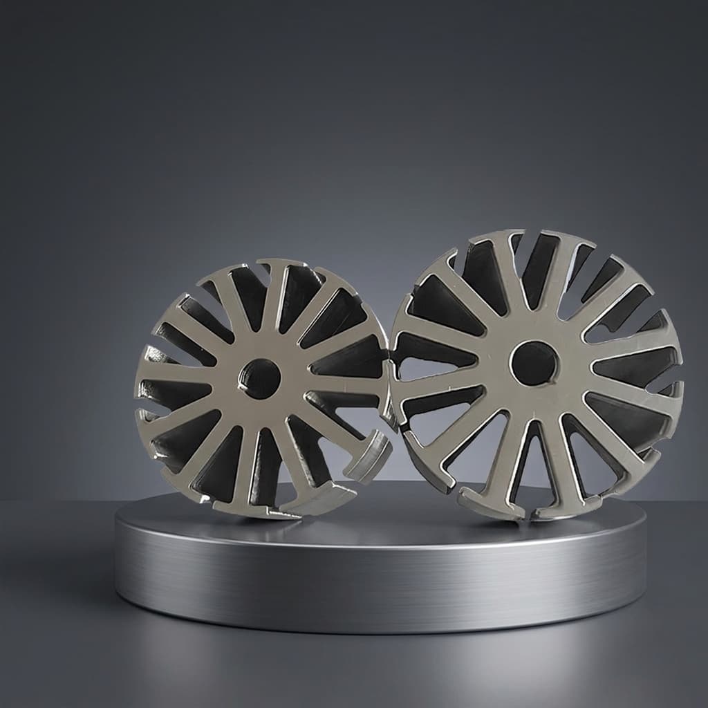
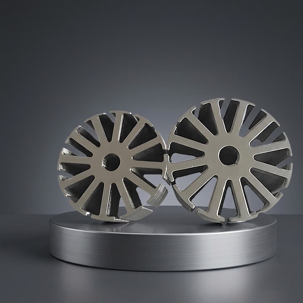
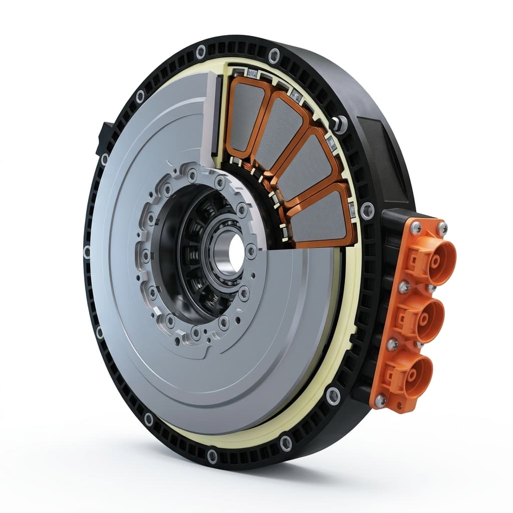
Figure 1: Existing product illustration of slotted axial flux core components. It does not show separate retained teeth, bond lines or an assembled potted module, and is not evidence of a qualified retention design. See Figure 2 for retention concepts.
As a separate geometric screening example, a 0.08° rotation across a 40 mm lever arm gives 40 × tan(0.08°) ≈ 0.056 mm displacement. Whether that motion reduces axial clearance depends on the rotation axis and location. It does not prove rotor contact in an assumed 0.80 mm gap; compare the full tolerance, runout, thermal and elastic deflection budget.
2. Thermal-Mechanical Strain and CTE Mismatch
Thermal expansion mismatch is a credible driver of interfacial stress and fatigue, alongside mechanical overload, cure shrinkage, vibration and chemical aging. It must be assessed for the actual SMC grade, carrier, coil and cured compound.
2.1 Reproducible free-expansion estimate
Use the following illustrative inputs, held constant over the temperature range: carrier CTE 23 × 10⁻⁶ /K, tooth CTE 11 × 10⁻⁶ /K, engagement length 35 mm, bond thickness 0.15 mm, and a temperature swing from −40°C to +150°C.
ΔT = 150 − (−40) = 190 K
Δε = (23 − 11) × 10⁻⁶ × 190 = 0.00228
ΔL = 0.00228 × 35 mm = 0.0798 mm ≈ 80 µm
gamma_screen = ΔL / 0.15 mm = 0.532 ≈ 53%
The last line assumes all relative free expansion is taken across the bond layer. It is a kinematic screening ratio, not a solved joint strain, shear stress or fatigue-life prediction. Real joints redistribute displacement through housing flexibility, contact, polymer viscoelasticity and temperature gradients. Cure temperature and residual stress also matter. Use temperature-dependent properties and representative joint testing before specifying a bond-line thickness.
2.2 Direct cooling adds a chemical boundary
A debonded interface can change heat transfer, stiffness and leakage behavior. Its effect depends on the heat path and coolant access; no fixed temperature rise follows from delamination alone.
For direct oil cooling, qualify the complete cured joint in the named coolant and additive package at the specified exposure temperature and duration. Record swelling, cracking, mass/dimensional change, bond strength, dielectric behavior and leakage before and after exposure. Resin-family names cannot establish compatibility with every ATF or synthetic coolant.
3. Structural Schematics: Forces, Thermal Vectors, and Mechanical Interlocking
Figure 2 separates the tooth load directions from three possible retention concepts. It is an explanatory schematic, not a YASA production drawing or a supplier capability certification. On a narrow screen, scroll horizontally to read the labels.
Figure 2: Conceptual tooth forces, illustrative CTE inputs, and retention routes. A dovetail, resin key or cage still requires an explicit connection to the motor housing; an outer band alone does not establish torque reaction.
4. Mechanical Interlocking Architectures and SMC Manufacturing Limits
Positive mechanical engagement can reduce reliance on an exposed planar bond line. It also creates local bearing loads and stress concentrations that must remain acceptable in the tooth, resin and carrier. The YASA over-moulding patent, especially Figures 6–10, describes molded shoe pockets, locating features and local reinforcement. A disclosed construction is evidence of a design approach, not its load capacity or service life.
Höganäs describes SMC as insulated iron powder that supports complex shapes and three-dimensional magnetic circuits. This does not mean every undercut can be pressed and ejected. Review press direction, density gradients, minimum sections, tooling splits and green-part handling before selecting a dovetail. Laminated teeth may use stamped features, clamps or separate retainers; secondary machining is not inevitable.
Table 1: Retention Architecture Decision Matrix
These are design options for review, not ranked test results. Capacity and envelope must come from the project drawing and qualification evidence.
| Architecture | Intended reaction path | Main engineering question | Manufacturing control | Evidence to request |
|---|---|---|---|---|
| Planar adhesive bond | Bond transfers force to carrier | How are peel, creep and aging handled? | Bond thickness, preparation and cure | Hot/aged joint fatigue and displacement data |
| Dovetail or keyed root | Contact transfers force to carrier | Can the SMC root survive bearing and bending? | Die release, root radii and mating clearance | Root stress analysis and directional proof tests |
| Stepped potting shoulder | Resin key reacts against tooth ledge | Will the resin key creep, shear or crack? | Fillet geometry, filling and cure shrinkage | Hot/aged key tests and sectioned fill evidence |
| Molded clamshell pocket | Pocket locates tooth and connects to housing | Are seams, fasteners and hot polymer stiffness adequate? | Mold shrinkage, inserts and mounting datums | Assembly stiffness, leakage and retention tests |
| Circumferential fiber band | Hoop restraint supplements another torque path | Where does tangential reaction enter the housing? | Fiber placement, preload and cure | Band/interface analysis and thermal-cycle tests |
| Separate clamp or pin | Retainer connects tooth to carrier | Are local stresses and electrical clearances acceptable? | Preload, contact area and insulation protection | Retainer fatigue, preload retention and dielectric tests |
A stator is stationary: rotor centrifugal containment is not a reason to specify its outer band. Select an architecture by demonstrated load path and service conditions, rather than assuming an automotive or aerospace label proves suitability.
5. Structural Potting Chemistry, Resin Selection and Processing
Potting can contribute insulation, heat conduction, vibration control, environmental sealing and structural support. Assign these functions explicitly: a thermally conductive encapsulant is not automatically a structural adhesive, and an injection-overmolded clamshell is a different process from thermoset potting.
5.1 Glass transition and retained properties
Request the cured glass-transition temperature (Tg) with its measurement method and cure schedule. DSC and DMA can report different transition values; compare like methods. Modulus and creep behavior change around Tg, but neither a fixed percentage strength loss nor a universal temperature margin applies to every compound.
For example, a buyer choosing a 25°C screening margin above a 175°C maximum relevant compound temperature would request Tg ≥ 200°C. That is an RFQ assumption, not a standard or release criterion. Confirm the compound's actual temperature distribution, exposure duration, retained modulus, fatigue and electrical performance. A winding hotspot does not necessarily equal the temperature of every retention joint.
5.2 Conductivity, filling and cure trade-offs
Mineral fillers can change thermal conductivity, CTE, viscosity, settling and dispensing wear. Obtain values for the fully cured named formulation at relevant temperatures, with test methods and filler disclosure where available. Higher conductivity is useful only if the process fills the required paths without unacceptable voids or segregation.
Develop the dispensing temperature, mix ratio, vacuum/pressure schedule, fill direction and cure cycle with the compound supplier. VPI and vacuum casting are options, not interchangeable guarantees of complete filling. Validate coil wetting, cure exotherm, shrinkage, insulation compatibility and final dimensions on representative sectors.
Table 2: Six Resin-System Sourcing Questions
No numerical properties or coolant ratings can be inferred from chemistry alone. Each row identifies evidence to obtain for an actual commercial grade.
| Candidate system | Reason to evaluate | Main trade-off | Required supplier evidence |
|---|---|---|---|
| Bisphenol-A epoxy system | Available structural and encapsulation formulations | Cure and modifiers strongly affect hot behavior | Tg method, retained modulus and hot joint data |
| Epoxy novolac system | Candidate when elevated-temperature properties are needed | Cure temperature, toughness and residual stress | Full cure schedule, shrinkage and aged joint results |
| Mineral-filled epoxy system | Candidate for thermal-path and CTE control | Viscosity, filler settling and incomplete wetting | Cured conductivity/CTE, rheology and fill validation |
| Cycloaliphatic epoxy system | Candidate for electrical encapsulation | Dielectric performance does not establish joint durability | Electrical aging plus mechanical/coolant joint tests |
| Polyurethane system | Candidate where compliance or vibration accommodation matters | Hot creep, moisture and chemistry limits vary | Temperature-duration envelope and compatibility tests |
| BMI or cyanate ester system | Candidate for a demanding thermal envelope | Cure burden, brittleness, process compatibility and cost | Grade-specific processing, toughness and exposure data |
For procurement, compare cost per accepted assembly, including dispensing time, cure capacity, inspection and scrap, rather than resin price per kilogram alone. If no supplier has representative hot/aged data, send the duty envelope for a qualification-scope discussion before freezing the compound and tooling.
6. Surface Preparation and Insulation Preservation
SMC particle insulation is part of the magnetic material system. Do not assume grit blasting, machining, chemical etching or plasma treatment leaves that system unchanged. Any surface treatment should be agreed with the core and adhesive suppliers and assessed for bond performance, core loss and electrical insulation.
6.1 Define a qualified process instead of a universal recipe
- Clean and handle: Identify powder residue, release agents, oils and other contaminants. Select a cleaning method compatible with the actual core coating and insulation system.
- Assess wetting: Use a suitable, repeatable cleanliness/wetting method. A dyne reading on a rough or porous SMC surface does not certify adhesion or magnetic performance.
- Evaluate activation or primer if needed: Plasma and silane primers are candidates, not mandatory steps. Qualify treatment dose, coverage, drying, time to bonding and compatibility with the resin and coolant.
- Verify the complete joint: Compare representative untreated and treated parts after thermal/fluid aging. Record failure location and check that treatment has not caused unacceptable core-loss or insulation changes.
The released process should name consumables, equipment settings, storage limits, preparation-to-potting time and change-control triggers. No surface-energy threshold guarantees a particular MPa bond strength.
7. Qualification Metrology and Factory Acceptance Testing
Separate design qualification from routine production acceptance. The motor owner should approve test severity, sample size, measurement uncertainty and release limits based on the duty spectrum and failure consequences.
7.1 Representative retention tests, distinct from ASTM D1002
ASTM D1002-10(2019) concerns comparative apparent shear strength of metal-to-metal single-lap specimens loaded in tension. Its scope is not a stator tooth push-out certification; coupon strength cannot simply be used as an allowable stress for a different joint.
Use coupons to screen compatible materials and preparation processes. For actual retention, define a separate sector or assembly test:
- Support the carrier as it is supported in the motor; avoid a fixture that artificially reinforces the joint.
- Specify axial and tangential loading separately, the load application point, rate, temperature, conditioning and displacement measurement.
- Derive proof and ultimate loads from the applicable directional fault/operating load cases and an approved safety factor. The worked example does not establish a 12 kN/tooth minimum.
- Repeat relevant tests after thermal cycling, torque fatigue and coolant aging. Record displacement, stiffness and failure mode; a high ultimate load can hide unacceptable movement at service load.
7.2 Thermal cycling and shock
IEC 60068-2-14 is a change-of-temperature test-method family. Specify the edition and method with the test laboratory; it does not supply a universal automotive stator qualification schedule.
The −40°C to +150°C envelope in the calculation is an example, not a prescribed test profile. Select limits, dwell based on specimen stabilization, transfer/ramp conditions, cycle count and acceptance criteria for the actual assembly. Rapid two-chamber shock and controlled-rate cycling impose different conditions. Compare retention, dimensions, leakage, insulation and magnetic loss before and after the agreed exposure; do not claim life equivalence without a justified acceleration model.
7.3 Void inspection and electrical validation
Voids can affect structural load paths, heat transfer and dielectric behavior. Define critical zones and inspectability, not just an assembly-average porosity number. CT capability depends on part size, attenuation, reconstruction and validated defect detection; voxel size alone is not detection resolution.
A proposed 0.5% total void limit may be a project screening target, but it is not a universal acceptance criterion for 400/800 V stators. Void location, shape, connection to a bond edge and electric field matter. Correlate CT or destructive sections with mechanical, thermal and appropriate dielectric/partial-discharge tests under representative inverter waveforms. Nominal bus voltage alone cannot establish an acceptable void size.
8. Procurement and Engineering Acceptance Checklist
Use these ten RFQ gates to identify missing decisions. Attach numerical limits only after the motor owner and supplier agree how they will be verified.
- 1. Load budget: Supply rated, peak and fault torque waveforms, axial loads, duration, cycles and tooth load-sharing assumptions.
- 2. Reaction path: Mark tooth-to-housing contacts, joints and mounts; identify what carries load if adhesion degrades.
- 3. Pressability: Confirm tool opening/ejection direction, undercuts, root radii, density and secondary-operation controls for the actual SMC geometry.
- 4. Datums and clearance: Define carrier/tooth datums and tolerances from the running air-gap budget, including thermal and elastic movement.
- 5. Compound identity: Name formulation, revision, cure, Tg method and retained mechanical/electrical properties at relevant temperatures.
- 6. Thermal and fluid boundary: Name coolant, additives, exposure conditions, required thermal path and aging evidence.
- 7. Surface preparation: Release compatible cleaning/activation/primer steps and verify bond, core-loss and insulation effects.
- 8. Filling and void control: Define critical zones, process window, inspection capability, acceptance limits and production sampling.
- 9. Retention testing: Agree fixture, directions, rates, conditioning, permissible service displacement and proof/ultimate loads.
- 10. Release and changes: Agree qualification evidence, lot traceability and requalification triggers for core grade, resin, coolant, treatment, tooling or cure changes.
9. Frequently Asked Questions
Can structural epoxy replace mechanical interlocking entirely in a yokeless stator?
It can only be judged against a defined joint and duty envelope. Adhesive-only retention requires evidence for hot creep, cyclic peel/shear, fluid aging and service displacement, plus acceptable consequences if the bond degrades. Mechanical engagement offers another load path but still needs local stress and fatigue qualification. Neither a room-temperature coupon result nor an interlock label proves reliability.
How does thermal cycling affect an SMC-to-resin joint?
Different thermal expansion, cure shrinkage and changing polymer stiffness create cyclic joint stresses. The example above gives about 80 µm of differential free movement across 35 mm for the assumed CTEs and 190 K swing. That is not measured joint motion or a fatigue-life result. Use actual temperature-dependent properties, constraints and conditioned joint tests.
Is SMC always better than laminated steel for retained modular teeth?
No. SMC offers three-dimensional magnetic and shaping opportunities, but ejection constraints, local strength, core loss and tooling cost still matter. Laminated alternatives may use stamped, clamped or separate retention parts. Compare total motor requirements and qualified manufacturing routes rather than assuming all dovetails are net-shape pressable.
What is the maximum acceptable void percentage in stator potting?
There is no single percentage that approves every stator. The 0.5% example is a possible project target only after defining the measurement, critical regions and correlation to functional tests. A small void in a high-field or highly stressed location can matter more than the same void volume elsewhere.
How does direct oil cooling affect potting selection?
It makes the specific coolant formulation, temperature and exposure time part of compound and joint qualification. Ask for aged retention, swelling, insulation and leakage results for the actual core/coating/resin combination. A generic epoxy, novolac or polyurethane family description does not prove or disprove compatibility.
10. Sources and Evidence Boundaries
- US9287755B2 — Electric machine—over-moulding construction, YASA Motors Ltd; Woolmer, Gardner and Barker; published March 15, 2016. Figures 6–10 and the associated description support the discussion of overmolded pockets, locating features and local reinforcement. They do not establish numerical retention capacity, universal resin specifications or production-life results.
- ASTM D1002-10(2019) — Apparent Shear Strength of Single-Lap-Joint Adhesively Bonded Metal Specimens by Tension Loading (Metal-to-Metal), ASTM International. Scope 1.1 and significance/use 4.1–4.5 support comparative coupon screening and the limits of transferring coupon strength to a different structural joint. This is not a push-out standard for SMC assemblies. The legacy URL may restrict automated access; the publisher's catalogue record identifies the same edition.
- Soft magnetic materials — technology overview, Höganäs AB. Supports insulated-particle SMC construction, complex-shape manufacture and three-dimensional magnetic design. This overview is not a grade datasheet and does not establish the illustrative CTE inputs, mechanical strengths or a particular retention geometry's pressability.
Evidence boundary: Reviewed November 1, 2026. Sources support the construction concepts and test-method boundaries identified above. The force, tilt and CTE arithmetic is reproducible engineering screening using stated assumptions; the decision matrices and RFQ gates are editorial engineering recommendations. No supplier grade property table, physical endurance test, customer result or universal qualification limit is claimed. IEC test conditions must be agreed with a laboratory against the specified edition; no standard is presented as mandating the example temperatures, cycle count or porosity. Review this guidance when the design, compound, coolant or referenced methods change.
11. Engineering Review and Yokeless Stator Sourcing Next Steps
For an actionable RFQ, send tooth and carrier CAD, reaction-load waveforms, temperature/coolant limits, the running-clearance budget and the proposed acceptance plan. Flag which properties are assumptions and which have test reports. That lets the core supplier, potting supplier and motor owner resolve missing evidence before serial release.
Send your stator CAD and duty envelope for a DFM review to discuss pressability, retention features and the required qualification scope. Review the compaction tooling DFM guide, manufacturing quality controls, and AFPM SMC stator solutions when preparing the drawing and evidence package.
Article-to-RFQ Workflow
Turn this guide into an evidence-ready RFQ.
Use the article context as the starting point, then align CAD status, magnetic targets, validation scope, and release records before asking suppliers to quote.
Capture the decision
Identify the topology, product family, operating point, and current gate before the article takeaway becomes a supplier question.
Attach buyer inputs
Prepare drawing status, magnetic targets, quantity plan, destination, and open risks in the RFQ worksheet.
Request evidence
Ask for DFM notes, first article inspection, magnetic validation, traceability, and packaging release files before price comparison.
Author

Categories
More Posts
Thermal Management in Axial Flux Motors: Direct Oil Cooling and Stator Core Design
Engineering guide to axial flux motor thermal management, direct oil cooling, SMC stator design, validation risks, supplier evidence, and RFQ checks for buyers.
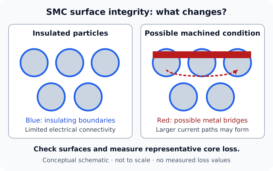
SMC Stator Core Machining vs. Net-Shape Compaction: Surface Particle Smearing, Eddy Current Traps, Chemical Etching, and Prototyping Sourcing Economics
Compare SMC stator machining and net-shape compaction, assess surface smearing and eddy losses, and plan prototype validation costs. Request a drawing review.
Foxconn-Magnax and PanGood: Axial Flux Motor Mass Production Scales Up
Foxconn-Magnax and PanGood show axial flux motor mass production moving into Asian foundries. Compare capacity, sourcing risks, RFQ actions, and evidence gaps.