
Axial Flux Stator Slot Insulation and PDIV in 800V SiC Systems: Epoxy Powder Coating vs. Slot Liners, Edge Radii, and Sourcing Controls
Compare axial flux stator slot insulation and PDIV for 800V SiC drives. Evaluate powder coating, liners and edge controls, then prepare your drawing-led RFQ.
Decision-level summary: Axial flux stator slot insulation for an 800V SiC drive must be selected against the voltage waveform at the winding, assembly damage risks, and the complete insulation system. Epoxy powder coating can conform to segmented teeth and reduce assembly clearance, but thin edges, pinholes, and winding abrasion can defeat those benefits. Slot liners and molded bobbins remain viable when their fit, overlap, and interfaces are qualified. Specify a measurable corner geometry and local coating thickness, then request repetitive partial discharge inception voltage (RPDIV) evidence on representative wound samples. Neither an 800V label, a fixed edge radius, nor a Hipot pass establishes pulse-voltage qualification.
Published and reviewed: November 3, 2026. Scope: Global B2B engineering, procurement, and supplier quality teams specifying segmented SMC or electrical-steel axial flux stators for 800V-class SiC drives. The same review questions apply to 1200V-class designs, but their electrical stresses require separate analysis. This is a sourcing and design-review guide, not a certification report. The worked calculations are hypothetical screening examples; no measured motor, coating, or RPDIV dataset is presented. Standards references establish test scope, not universal acceptance numbers.
Preparing an 800V stator RFQ or prototyping a concentrated tooth design? Request a drawing-led DFM review with your tooth CAD, voltage profile, inverter switching speed, and slot geometry. Review our compaction tooling DFM guide, manufacturing quality controls, and AFPM SMC stator solutions for tooling and fabrication planning.
1. The High-Voltage SiC Inverter Environment and Dielectric Stress
A nominal DC bus voltage does not describe the stress between adjacent turns, between phases, or between a winding and its grounded core. Fast switching, the inverter-to-motor cable, winding impedance, grounding, and modulation all influence the waveform that reaches the insulation. Collect these conditions before comparing coating quotes:
- Voltage rise time and amplitude: Record the voltage step and how rise time is measured. As an arithmetic example, an 800V step in 20 ns gives an average slew rate of 40 kV/µs. A rise-time convention using only part of the voltage transition changes the calculation. There is no single slew rate shared by all SiC drives.
- Cable reflections: For a single incident step, a simplified transmission-line model gives
V_terminal = V_incident × (1 + Γ_L), whereΓ_L = (Z_load − Z_cable) / (Z_load + Z_cable). A high positive reflection can approach voltage doubling. This is an illustrative limit for that model, not a prediction that every 800V motor sees 1600V. Cable length, damping, pulse spacing, and repeated reflections matter. - Winding voltage distribution: A fast front can distribute unevenly across the winding. Use an appropriate winding model or measurements rather than assigning a fixed percentage of terminal voltage to the first turns. Keep turn-to-turn, phase-to-phase, and phase-to-ground stresses separate.
- Insulation system category: IEC 60034-18-41 addresses qualification and quality control for Type I converter-fed winding insulation. Confirm that this category and the selected edition apply to the actual machine. Do not assign a category solely from bus voltage, resin chemistry, or motor topology.
PDIV describes the onset of partial discharge under stated test conditions; RPDIV refers specifically to repetitive impulse excitation. A sinusoidal PDIV value cannot be substituted directly for a repetitive-pulse result. Record polarity, peak versus peak-to-peak voltage convention, repetition rate, rise time, temperature, pressure, and detection method beside every result.
Partial discharge can progressively erode an organic insulation system. Its inception and damage rate depend on void geometry, material interfaces, environment, and electrical stress. Without endurance data, avoid promising a specific failure time or claiming that dielectric failure replaces thermal, magnetic, and mechanical limits as the dominant motor failure mode.
2. Axial Flux Stator Geometry: Where Slot Liner Fit Becomes Difficult
In many radial flux stators, folded dielectric sheets are inserted into relatively straight slots. In segmented axial flux machines, tapered tooth flanks, pole-shoe overhangs, and retention features can make a flat-sheet approach harder to assemble consistently. The appropriate response depends on the actual tooth and winding route; three-dimensional geometry does not make every liner design unsuitable.
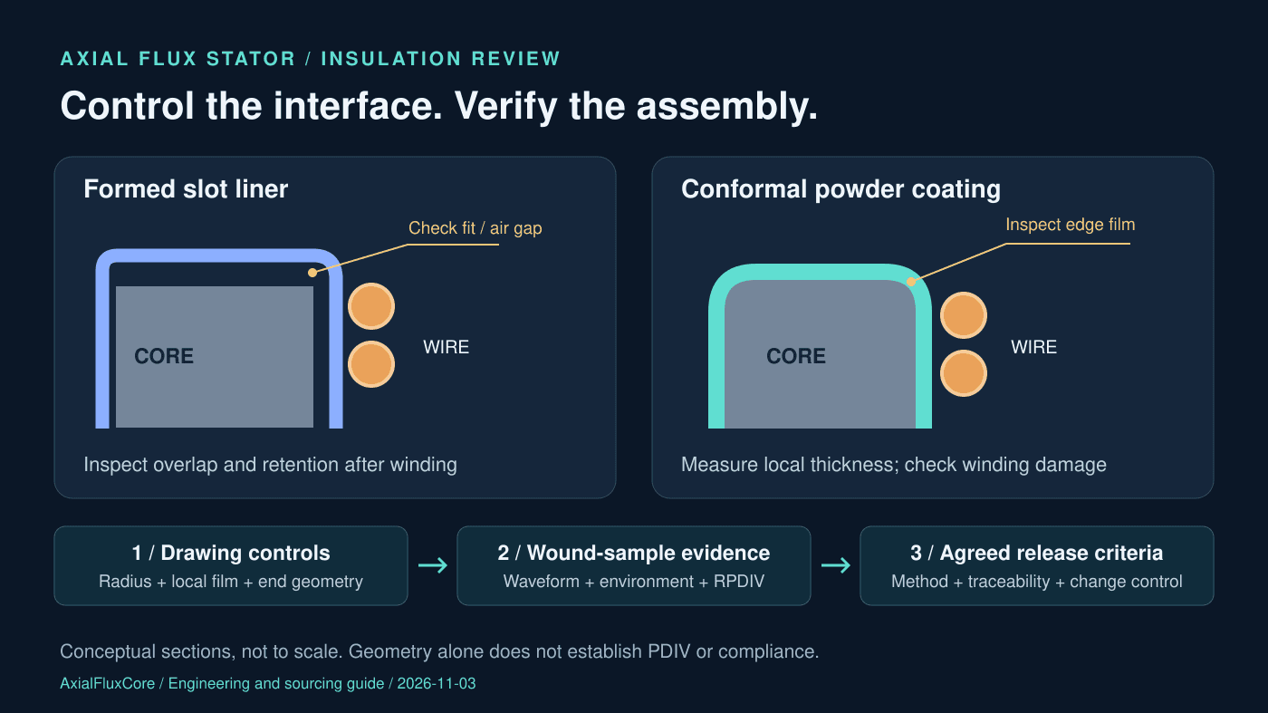
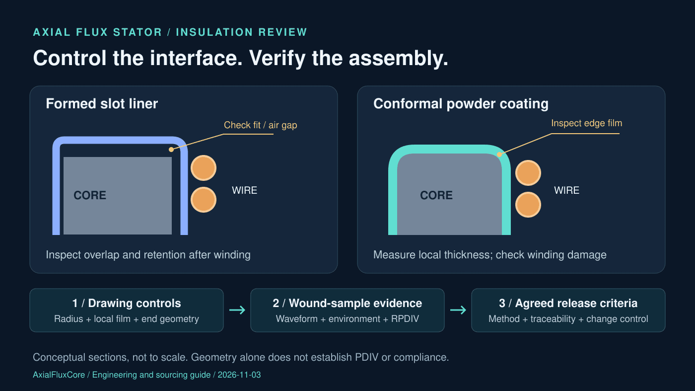
Figure 1: Original design-review schematic, not to scale. The liner interface and coating edge are inspection locations, not measured defects. Rounded geometry can help coating coverage, but RPDIV must be measured on the assembled insulation system.
2.1 The 3D Tapered Slot Geometry
As the circumference increases from the inner to the outer radius, annular tooth layouts can create tapered winding spaces. Shoe overhangs restrict insertion access, and transitions into mounting features can sit close to the conductor path. Review the minimum winding envelope at each radial position instead of quoting a single slot width.
Include insulation overlaps, end extensions, winding nozzle clearance, and the maximum finished coating envelope in the CAD review. Creepage and clearance also depend on the exposed end geometry. A coating specification on the tooth flank does not resolve an inadequate end-turn separation.
2.2 Mechanical Risks of Folded Slot Liners in Segmented Cores
The practical comparison is between controlled manufacturing processes. Inspect the following risks on trial assemblies:
- Creasing and buckling: A cut or folded sheet may wrinkle around a compound transition. Custom forming, relief cuts, and retaining features can help, but each needs an approved assembly method.
- Spring-back and interface air: A liner can lift from a corner. In an ideal layered dielectric with no free interface charge, the normal field ratio follows the permittivity ratio. Assuming solid relative permittivity of 3.5 and air of 1 gives a local field ratio of 3.5. This simplified relation does not establish whether a real cavity will discharge; cavity dimensions, pressure, and waveform remain necessary.
- Winding damage: Wire tension, wire diameter, enamel build, guide alignment, and contact geometry determine abrasion risk. Establish tension limits through winding trials, then examine insulation after winding rather than relying only on incoming core inspection.
- Occupied slot area: Compare the complete liner-plus-clearance envelope against the maximum coated envelope. For a hypothetical two-sided slot, replacing a 0.40 mm envelope per side with 0.20 mm recovers 0.40 mm total width. That dimensional gain alone does not predict copper fill, temperature, or motor efficiency.
3. Electrostatic Epoxy Powder Coating: Edge Pullback and Dielectric Behavior
Powder coating applies a thermosetting insulating layer to the core and cures it to the required state. Electrostatic spraying and fluidized-bed application have different access, build, and masking behavior. Agree which route is quoted. A coating can remove the need for a separate liner in a qualified design, but it is not inherently void-free and does not replace turn insulation on magnet wire.
Thermal conductivity, dielectric strength, moisture behavior, and cure schedule belong to a specific formulation and test condition. Do not compare a resin's bulk conductivity with the effective conductivity of a loose liner-plus-air interface as though these were equivalent measurements. Request both material data and a representative assembly thermal assessment when temperature rise drives the decision.
3.1 The Edge Pullback Mechanism
During melt and flow before gelation, a coating can become thinner at convex edges. Surface tension, melt viscosity, wetting, particle distribution, substrate condition, and cure history all affect the result. A smooth radius can improve coverage, but no universal radius guarantees a particular edge retention ratio.
Define edge retention as minimum local edge thickness / reference flat thickness, measured at agreed locations. For example, a 200 µm flat and a 50 µm corner give 25% retention; a 150 µm corner on the same flat gives 75%. These are arithmetic examples, not expected production capabilities. Require cross-sections or another validated method to determine what the supplier actually achieves.
The coating drawing should distinguish minimum dielectric coverage from maximum dimensional build. Increasing average thickness may consume winding space without fixing a localized thin edge. Masking boundaries, recesses, and areas exposed to handling need their own inspection locations.
3.2 Electric Field Intensification at Sharp Edges
Curvature and local film thickness both influence field distribution. A useful analytical illustration treats the conductors as concentric cylinders with a homogeneous dielectric:
E_inner = V / [r × ln(1 + d/r)]

V: applied conductor-to-conductor voltage, in kV
r: inner conductor radius, in mm
d: radial dielectric thickness, in mm
E_inner: field at the inner conductor, in kV/mm
For the hypothetical inputs V = 1.6 kV, r = 1.0 mm, and d = 0.150 mm, this model gives about 11.45 kV/mm. It represents neither a real tooth-and-wire geometry nor a partial discharge criterion. A grounded tooth and discrete round wires introduce interfaces and field directions that this model omits.
Use the model to expose sensitivity to thin insulation, then move to the actual geometry. A calculated field below a bulk resin breakdown value cannot establish PD-free operation in a cavity, at an interface, or after winding damage. There is no conversion from this field equation to RPDIV without additional physical and experimental evidence.
4. Insulation Architecture Trade-off Matrix
These six routes are candidates for supplier discussion, not a performance ranking. No generic wall thickness, RPDIV, slot fill, or tooling price is assigned because those values require the same drawing, production quantity, material grade, and validation basis across quotes.
| Insulation architecture | Potential reason to select it | Main integration risk | Evidence to request before selection |
|---|---|---|---|
| Electrostatic epoxy powder coating | Conformal coverage with fewer separate assembly parts | Edge thinning, spray access, pinholes, winding abrasion | Local thickness map, cure records, wound-sample pulse testing |
| Injection-molded bobbin | Defined wire guides and repeatable assembly features | Wall and assembly space, seams, air at the core interface | Molded dimensions, fit sections, assembled thermal and electrical tests |
| Custom folded or formed slot liner | Flexible prototype changes and established sheet grades | Creases, overlap variation, movement during winding | Forming instructions, overlap inspection, post-winding damage checks |
| Fluidized-bed epoxy coating | Alternative deposition route for accessible tooth shapes | Build variation, masking and pooling at transitions | Coverage trials, finished dimensions, corner sections |
| Direct core overmolding | Integrated insulating and locating features | Processing load on the core, shrinkage, thermal expansion mismatch | Core-integrity checks, interface sections, aged assembly tests |
| Polyimide or glass-based tape system | Adaptable prototype wrapping and local reinforcement | Operator-dependent overlap and trapped interfaces | Controlled wrapping procedure, traceability, representative qualification |
A liner may be the lower-risk choice when geometry permits secure positioning and a supplier already has relevant qualification evidence. Powder coating becomes attractive when assembly clearance or complex contours constrain the winding. A hybrid system may also be appropriate: a coating on the core plus a local sleeve or protective end feature. Test the hybrid as supplied rather than combining separate component ratings.
For procurement, compare total delivered scope: core preparation, masking, coating, cure, inspection, scrap allowance, fixtures, winding support, and external laboratory work. A low coating price with no post-winding evidence can shift cost into later assembly rejection. Ask bidders to identify exclusions before comparing piece prices.
5. SMC Compaction Tooling DFM: Edge Radii, Punches, and Chamfers
Insulation geometry should enter the compaction discussion before the drawing is frozen. Höganäs' soft magnetic materials overview explains the use of insulated powder particles for SMC components and their three-dimensional design flexibility. That inter-particle insulation serves the magnetic material; it does not establish the finished tooth's winding-to-core voltage rating.
5.1 The Punch Tooling Feather-Edge Limitation
Thin tooling features, abrupt transitions, and difficult ejection paths can increase chipping or burr risks. Tool feasibility depends on press direction, powder grade, density target, tool material, and part geometry. Do not infer a fixed tool life, guaranteed burr height, or press speed from an edge radius alone.
Ask the tooling supplier to mark vulnerable punch features and explain how they will inspect trial parts. The coating provider should review those same locations. An apparently small chip can alter both the mechanical conductor-contact surface and the local coverage, while aggressive deburring can change the intended profile or damage the substrate.
5.2 Compaction Die Design Guidelines for Insulated Teeth
- Define the finished edge: Show a true radius, its tolerance, and the inspection method where conductors contact the core. A candidate 1.0 mm radius can be evaluated in a trial drawing, but it is not an IEC minimum or a universal coating rule.
- Review chamfers explicitly: A chamfer introduces two transitions. If selected for tooling or magnetic reasons, inspect coverage at both transitions rather than assuming it behaves like a smooth radius.
- Coordinate press and ejection geometry: Agree draft, die splits, retention features, and critical dimensions with the toolmaker. Do not add generic draft to mating surfaces without checking assembly fit.
- Protect material properties: Select lubrication, heat treatment, and surface preparation with the SMC grade supplier. Unvalidated blasting or thermal cleaning can affect particle insulation, surface condition, or magnetic performance.
- Close the magnetic trade-off: Removing material at a radius changes the tooth section. Review flux density, saturation margin, winding space, and dimensional tolerances together before releasing a geometry change.
Before authorizing tooling, request a compaction and insulation DFM review with marked conductor-contact edges and the intended coating envelope. Ask for open issues and a trial evidence plan alongside the quotation.
6. Dielectric Stress Screening: Corner Radius and Coating Thickness
The table below is a reproducible sensitivity exercise using the cylinder equation in section 3.2. Voltage is fixed at 1.6 kV. The radius and thickness inputs are independent, hypothetical choices; increasing radius is not assumed to produce the listed thickness. No row represents a tested tooth or an IEC pass.
| Example | Radius r (mm) | Assumed local thickness d (µm) | Calculated E_inner (kV/mm) | Interpretation |
|---|---|---|---|---|
| A | 0.10 | 50 | 39.46 | Small radius and thin dielectric combine in this model |
| B | 0.30 | 50 | 34.60 | More radius alone leaves a thin layer |
| C | 1.00 | 50 | 32.79 | Local thickness remains influential |
| D | 1.00 | 100 | 16.79 | Thickness change at the same radius |
| E | 1.00 | 150 | 11.45 | Worked input example from section 3.2 |
| F | 1.50 | 150 | 11.19 | Further radius change with thickness fixed |
To reproduce example E, convert 150 µm to 0.150 mm, evaluate ln(1 + 0.150/1.00), and divide 1.6 by the resulting denominator. The significant figures reflect arithmetic precision, not manufacturing accuracy.
This exercise shows why an RFQ needs minimum local thickness as well as an edge radius. It does not identify a safe field threshold or predict RPDIV. Obtain measurements on representative wound assemblies at the specified environmental conditions. If the application needs a 1600V repetitive stress withstand condition, report the relevant RPDIV margin on the same voltage convention; a room-temperature result above that value does not resolve a lower result at another required condition.
7. Factory Acceptance Testing and Quality Control Metrology
Separate incoming core checks, coating process controls, post-winding inspection, and system qualification. They detect different defects. A Hipot test can reveal insulation weakness and breakdown, but passing a low-frequency or DC withstand test does not establish behavior under repetitive fast pulses.
7.1 Holiday Testing: Choose the Method for the Coating
ASTM D5162-21 covers discontinuity detection on nonconductive coatings over conductive substrates. Its public scope generally assigns wet-sponge equipment to coatings up to 0.5 mm and high-voltage spark equipment to thicker coatings. It warns that high-voltage testing can damage thin films; the 0.25–0.5 mm exception requires appropriate settings and coating-manufacturer approval.
Consequently, a 200 µm coating must not automatically receive a 3 kV spark test labeled nondestructive. Agree an appropriate method with the coating manufacturer and test engineer, then validate that the procedure detects relevant defects without degrading acceptable parts. A wet-sponge method also needs confirmation of suitability for the geometry, material, and subsequent drying process. Record electrode access, contact conditions, and any inaccessible regions.
7.2 Coating Thickness Measurement
ISO 2808:2019 describes coating thickness measurement methods. Select a method suited to the substrate and feature size. Magnetic induction may be useful on a suitable ferromagnetic substrate, but a flat-face probe reading cannot automatically establish the thickness at a small corner.
Define measurement locations on the drawing. Use geometry-matched calibration and validate corner readings against sections when needed. Record both local minima and dimensional maxima, along with measurement uncertainty and the agreed acceptance rule. A proposed inspection pattern should cover flanks, conductor-contact radii, recesses, and masking boundaries; the number of points depends on the part's risks.
7.3 Offline Repetitive Impulse PD Measurement
IEC TS 61934:2024 concerns offline electrical PD measurement under repetitive voltage impulses. Its catalogue description excludes optical and ultrasonic methods, and notes that charge-based measurements are not described in this edition. Do not attach a generic pC threshold or optical setup to this reference without a separately justified procedure.
Use a representative motorette or completed winding with documented wire, coating, assembly, and impregnation details. Specify the pulse waveform, detection bandwidth, background-noise assessment, voltage stepping, and inception criterion. Test temperature and pressure should match the qualification plan, including reduced-pressure conditions if relevant. Thermal class alone does not select a test temperature or establish the assembly's life.
As a project-selected arithmetic example, a margin factor of 1.25 applied to a 1600V peak stress gives a 2000V peak RPDIV target. That factor is not presented here as an IEC requirement. The applicable qualification procedure determines the actual stress factors, conditioning, and acceptance rules; compare only quantities using the same voltage definition and insulation path.
| Quality gate | What to control | Evidence required | Release decision |
|---|---|---|---|
| Bare core geometry | Radius, chips, burrs, conductor-contact surfaces | Drawing-linked dimensional and visual records | Hold parts outside the agreed profile |
| Coating thickness | Flat build, local minima, maximum envelope | Validated readings and selected sections | Apply location-specific drawing limits |
| Discontinuities | Pinholes and exposed substrate | Approved method, settings, sensitivity and coverage | Disposition defects under the agreed plan |
| Cure and adhesion | Cure state and coating-to-core integrity | Part thermal history and suitable adhesion evidence | Resolve incomplete cure or adhesion loss |
| Post-winding integrity | Abrasion, displacement and edge damage | Inspection after representative winding and assembly | Hold changes that introduce damage |
| Pulse qualification and aging | RPDIV under specified waveform and environment | Traceable test reports before and after required conditioning | Release only against the agreed system criteria |
Agree lot definition, sample size, acceptance number, and change triggers. A bare statement such as “10 pieces, AQL 0.65” is incomplete without a sampling scheme and lot context. Destructive sections and qualification testing also require a different sampling rationale from routine production screening.
8. 10-Point Engineering and Procurement RFQ Checklist
Use this checklist to align the motor designer, core supplier, coating provider, winding team, and test laboratory before serial tooling:
- 1. Voltage waveform: State maximum DC bus voltage, measured or modeled winding stress, cable configuration, rise-time convention, polarity, repetition rate, and grounding arrangement.
- 2. Insulation paths: Identify turn-to-turn, phase-to-phase, and winding-to-core requirements, plus end-turn creepage and clearance boundaries.
- 3. Finished edge geometry: Mark conductor-contact radii, tolerances, burr and chip limits, and acceptable inspection methods on the released drawing.
- 4. Material and process identity: Record the SMC or steel grade, coating formulation, wire enamel, liner or bobbin grade, impregnation material, and controlled process revisions.
- 5. Thickness envelope: Define minimum local dielectric coverage and maximum finished dimensions, with calibrated measurement locations and any destructive section plan.
- 6. Discontinuity screening: Agree a manufacturer-approved method and severity appropriate to the coating, including evidence that screening does not damage acceptable insulation.
- 7. Pulse-test report: Require representative assembly details, waveform and voltage conventions, noise assessment, environment, inception definition, results, and the applicable standard edition.
- 8. Environmental conditioning: Agree thermal cycling, humidity, pressure, vibration, and endurance exposures relevant to the application, with subsequent electrical checks.
- 9. Coolant compatibility: Identify the exact service fluid and additive package, exposure temperature and duration, then assess mechanical and electrical properties after aging.
- 10. Change control: Define requalification triggers for tooling, powder, coating, cure, winding tension, wire, impregnation, and test-method changes; agree customer-specific PPAP requirements where applicable.
For quote comparison, require each supplier to mark every item as included, excluded, or awaiting an input. This turns an apparently complete quotation into a reviewable scope without treating missing evidence as an assumed pass.
9. Frequently Asked Questions
Can an axial flux motor use conventional slot paper in an 800V SiC system?
Yes, if the complete insulation system is qualified for the actual electrical and environmental conditions. Check liner forming, overlap, retention, conductor contact, and end geometry on representative assemblies. A tapered tooth makes fit more demanding but does not prove a liner will fail. Compare the evidence for the proposed liner and coating routes instead of assuming one material family is universally superior.
Why is a standard Hipot leakage test insufficient for SiC motor sign-off?
Hipot and repetitive-pulse testing examine different conditions. A withstand result does not establish discharge inception under a steep repetitive waveform. Keep routine withstand screening in the control plan where appropriate, and use the applicable pulse qualification method for converter-fed operation. Do not claim a guaranteed service life from either single test.
How does SMC surface condition affect powder coating adhesion?
Loose powder, lubricant residue, moisture, surface texture, and preparation can affect coating application and adhesion. Obtain the grade supplier's preparation constraints and the coating provider's validated process. Do not assume that all SMC needs aggressive blasting or a fixed preheat temperature. Check adhesion and core properties after the actual preparation and cure sequence.
What is the trade-off between increasing edge radius and electromagnetic performance?
A larger radius removes magnetic material and changes the winding envelope. For a simplified rectangular section with four equally rounded corners, area removed relative to sharp corners is (4 − π) × r², provided the radii fit without overlap. Compare that area with the actual tooth section, then review saturation and winding access in the motor model. This geometric calculation predicts neither an efficiency improvement nor an insulation rating.
How does direct oil cooling affect powder-coated axial flux stators?
It adds fluid compatibility and aging requirements. Test the specified oil or coolant, including relevant additives, on representative cured and assembled materials. Inspect swelling, adhesion, cracking, and electrical behavior after exposure. Neither an epoxy family name nor a generic oil-resistance statement establishes compatibility, and cooling architecture alone does not justify a universal current-density limit.
What causes pinholes during powder coating?
Potential contributors include substrate outgassing, moisture, contamination, deposition conditions, and cure behavior. Determine the mechanism from part inspection and controlled process trials. Stabilize the process, validate defect detection, and review the result after winding. A blanket spray-voltage setting or a claim that inspection eliminates every pinhole is not a substitute for demonstrated process control.
10. Sources and Standards Reference
- IEC 60034-18-41:2014 — Type I converter-fed winding insulation, International Electrotechnical Commission. Catalogue scope supports the qualification and quality-control distinction. Confirm applicable amendments and contractual edition with the test laboratory.
- IEC TS 61934:2024 — Repetitive-impulse electrical PD measurement, IEC, third edition; linked catalogue package includes the redline version. Scope and edition notes support the measurement-method boundaries discussed above.
- ASTM D5162-21 — Coating discontinuity testing, ASTM International. The cited edition's public summary explains method selection and thin-film limitations. This is an edition-specific reference, not a claim that the 2021 edition is the latest.
- ISO 2808:2019 — Film thickness determination, International Organization for Standardization. Describes thickness measurement methods and their fields of application; does not set this article's coating acceptance limits.
- Soft magnetic materials overview, Höganäs. Manufacturer background on SMC materials and three-dimensional component design, not evidence of any finished stator's RPDIV or supplier coating capability.
Evidence boundary and engineering review: Reviewed November 3, 2026 against public publisher descriptions. Full standard clauses and customer-specific compliance requirements require the applicable documents and a qualified laboratory. The numerical examples and schematic are original analytical aids, not first-party test evidence, customer results, or compliance declarations. Revisit this guide when the cited standards or the specified materials, waveform, geometry, and validation plan change; check references at the next RFQ review.
11. Engineering Review and Sourcing Next Steps
An insulation RFQ should make responsibilities and missing evidence visible before tooling commitment. Start with the tooth drawing and the stress definition, then ask the proposed manufacturing and test partners to close the coverage, assembly, and qualification questions together.
- Send your stator tooth CAD: Identify conductor-contact edges, winding access, mounting features, and maximum finished insulation dimensions. Request pressability and coating-access feedback.
- Share the electrical and service envelope: Include voltage waveforms, cable and grounding arrangement, temperature, pressure, cooling fluid, and intended operating life. Identify unknown inputs explicitly.
- Agree a prototype evidence package: Define sample geometry, local thickness measurements, winding trials, conditioning, pulse-test responsibility, and release criteria. Confirm coating and laboratory scope in the quotation before treating either as supplied capability.
Request an engineering review for your high-voltage axial flux stator core, or consult our compaction tooling DFM guide, manufacturing quality controls, and AFPM SMC stator solutions to prepare your prototype RFQ.
Article-to-RFQ Workflow
Turn this guide into an evidence-ready RFQ.
Use the article context as the starting point, then align CAD status, magnetic targets, validation scope, and release records before asking suppliers to quote.
Capture the decision
Identify the topology, product family, operating point, and current gate before the article takeaway becomes a supplier question.
Attach buyer inputs
Prepare drawing status, magnetic targets, quantity plan, destination, and open risks in the RFQ worksheet.
Request evidence
Ask for DFM notes, first article inspection, magnetic validation, traceability, and packaging release files before price comparison.
Author

Categories
More Posts
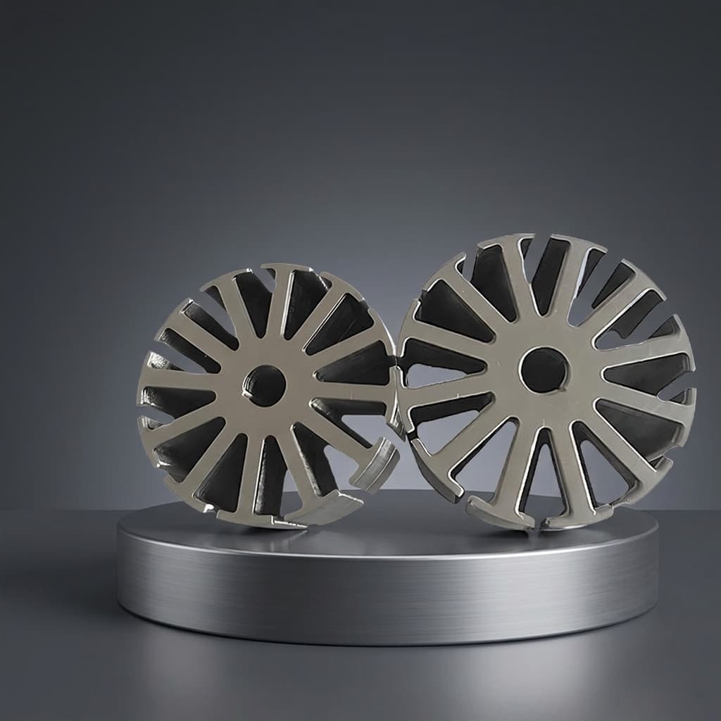
Axial Flux Motor Air Gap Tolerances and Unbalanced Magnetic Pull (UMP): Stator Core Flatness, Bearing Fatigue, and Sourcing Controls
Review axial flux air gap tolerances, UMP sensitivity, stator flatness and bearing fatigue. Use the sourcing checklist to prepare a drawing-led engineering RFQ.
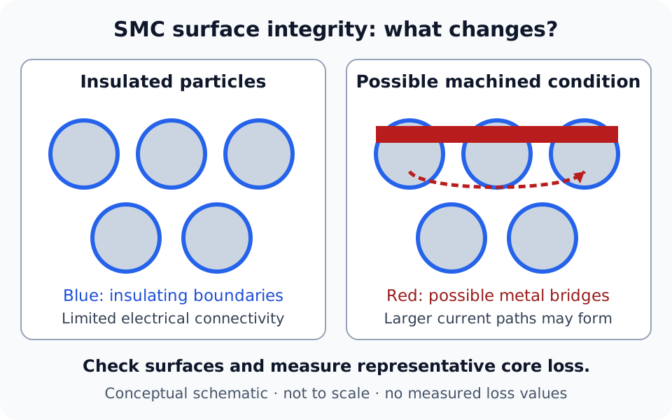
SMC Stator Core Machining vs. Net-Shape Compaction: Surface Particle Smearing, Eddy Current Traps, Chemical Etching, and Prototyping Sourcing Economics
Compare SMC stator machining and net-shape compaction, assess surface smearing and eddy losses, and plan prototype validation costs. Request a drawing review.
Direct Needle Winding on Segmented SMC Axial Flux Teeth: Slot Fill Factors, Wire Tension Fracture Limits, Corner Radius DFM, and Sourcing Controls
Compare direct needle winding on SMC axial flux teeth: copper fill, tension trials, corner radii and insulation. Prepare your drawing-led RFQ for DFM review.