
AFPM Core Performance Testing: Plan Your Tests
Plan AFPM core performance testing: estimate iron mass and frequency, add measured loss data, and export a laboratory brief.
Executive Testing Takeaways & Engineering Decisions
Four planning decisions drawn from method scopes and stated physical assumptions. Use the linked chapters to check evidence, limitations and the next measurement.
Select a method for the specimen, not the motor label
IEC 60404-6 addresses eligible ring specimens. A return-yoke tooth rig needs a validated procedure; complete motor efficiency is a separate measurement. See Chapters 2 and 15.
Treat missing measurements as unknown
The tool needs matching measured W/kg before it reports conditional total loss. Carrier frequency alone cannot determine material loss. See Chapters 3 and 4.
Keep geometry estimates separate from instrument ratings
Faraday voltage uses a supplied effective flux section. Neither stator envelope mass nor a voltage estimate establishes amplifier VA or electrical safety. See Chapters 1 and 5.
Agree the evidence and acceptance plan before testing
Record waveform, temperature, preload, specimen identity and uncertainty. Coupons, assembled stators and motors answer different release questions. See Chapters 6, 12 and 16.
Planning audiences (method scope still requires review)
- • OEM traction motor teams comparing segmented or annular stator cores.
- • Propulsion R&D teams planning a frequency and waveform test matrix.
- • Industrial robotics and precision servo actuators requiring high torque-to-inertia ratios.
- • Industrial drive buyers defining component evidence before motor validation.
Boundary Exclusions (Out of Scope for This Guide)
- • Generic grid-connected 50/60 Hz radial flux induction motor lamination testing.
- • Low-speed multi-megawatt direct-drive wind turbine generators without back-iron.
- • Consumer DIY hobbyist brushless DC (BLDC) drone outrunners without core laminations.
- • Third-party distributor marketplace pricing or commercial inventory listings.
In-Depth Engineering Chapters: AFPM Core Performance Testing
Sixteen chapters distinguish measured data, physical calculations and editorial planning guidance. Numeric acceptance limits and laboratory capabilities require agreement.
B-H loops: what the test actually measures
Separate measured flux and field from envelope-based planning estimates.
For a linked search coil, e2 = −N2 dΦ/dt. With a defined effective section, integration gives average B. Establish polarity, offset correction and the coil-linked area before comparing loops. Air-flux pickup and integration drift belong in the uncertainty budget.
For sinusoidal flux only, E_rms = 4.44288 f N Bpk Ac. The calculator uses this relation when the section is supplied. A PWM selection changes the interpretation to a fundamental reference; it does not predict pulse peaks or total RMS.
The tool estimates iron mass from annular envelope volume × iron volume fraction × density × stator count. The fill input represents occupied iron volume, not winding fill. Use weighed specimen mass and drawing-derived sections for acceptance work.
E_rms = 4.44288 × f × N × Bpk × Ac (Ac in m²; sine flux)Method sequence; no measured performance curve or invented data.
B-H loops: what the test actually measures — decision checklist
Editorial planning guidance; thresholds and test conditions require buyer/laboratory agreement.
| Item / method | What it establishes | Boundary / next evidence |
|---|---|---|
| Mass | Envelope + volume fraction | Replace with weighed specimen |
| Flux section | User-supplied effective area | Unknown if blank |
| H(B), current, VA | Not calculated | Measure fixture and winding response |
Note: No universal grade property, acceptance limit or laboratory capability is implied.
Sources support the stated method scope. Planning checklists and examples are editorial; no universal acceptance limits are asserted.
Choose a specimen: sheet, ring, tooth or assembly
Each fixture answers a different question and has different correction costs.
IEC 60404-6 covers selected metallic and powder ring materials and explicitly excludes electrical steels and soft ferrites. Calling every AFPM core test an IEC 60404-6 test would overstate applicability.
IEC 60404-2 concerns electrical steel sheet/strip in an Epstein frame; its public base scope specifies AC measurements up to 400 Hz. Cutting representative sheet samples does not reproduce tooth-edge damage, assembly stress or a multi-axis operational flux path.
A custom tooth fixture can preserve production geometry and reduce the material needed for an experiment. It also adds return-yoke loss, contact gaps, fixture heating and flux nonuniformity. Establish repeatability and a correlation to assembly measurements; no universal cost saving or correlation percentage is available.
Method sequence; no measured performance curve or invented data.
Choose a specimen: sheet, ring, tooth or assembly — decision checklist
Editorial planning guidance; thresholds and test conditions require buyer/laboratory agreement.
| Item / method | What it establishes | Boundary / next evidence |
|---|---|---|
| Electrical steel strip | Epstein/sheet method | Check frequency scope |
| Eligible SMC ring | IEC 60404-6 ring method | Not a whole motor result |
| Finished tooth | Custom return-yoke rig | Separate fixture-loss correction |
Note: No universal grade property, acceptance limit or laboratory capability is implied.
Sources support the stated method scope. Planning checklists and examples are editorial; no universal acceptance limits are asserted.
Loss models require fitted data
Use loss separation as a calibrated model, not a material lookup promise.
A hysteresis/classical/excess decomposition is one possible engineering model. Fit it to a documented set of measured frequency and B points, with consistent units, waveform, specimen processing and temperature.
No validated coefficients are provided here for Somaloy, NOES, amorphous or nanocrystalline products. Grade names alone do not determine a loss surface. The calculator accepts measured specific loss and applies P = p_specific × mass without a hidden correction.
Hold back independent points for checking residuals and disclose the fitted range. Do not extrapolate through saturation, change from alternating to rotational flux, or transfer coefficients between heat treatments without new evidence.
P_core = p_specific (W/kg) × m_iron (kg)Method sequence; no measured performance curve or invented data.
Loss models require fitted data — decision checklist
Editorial planning guidance; thresholds and test conditions require buyer/laboratory agreement.
| Item / method | What it establishes | Boundary / next evidence |
|---|---|---|
| Hysteresis term | Fit from measured loops | No grade coefficient supplied |
| Classical/excess terms | Model-dependent separation | Report parameter correlation |
| Outside fit range | Unknown | Measure additional points |
Note: No universal grade property, acceptance limit or laboratory capability is implied.
Sources support the stated method scope. Planning checklists and examples are editorial; no universal acceptance limits are asserted.
PWM: measure the waveform you intend to use
Avoid attributing a generic material loss penalty to a motor standard.
IEC 60034-2-3:2024 is an International Standard for converter-fed motor loss and efficiency methods. It is not “IEC TS 60034-2-3:2024”, and its public scope does not establish fixed material loss multipliers.
For a useful comparison, hold fundamental B, frequency, temperature, specimen and preload consistent while changing the recorded drive waveform. Capture carrier, modulation, DC bus and relevant switching behavior. The difference is specific to that experiment.
A sine datum must not be relabelled as PWM loss. Supply a matching PWM measurement to the tool or leave loss unknown. Changing waveform, carrier, frequency or B clears the supplied datum to prevent reuse at a different operating point.
Measured waveform ratio = P_PWM / P_sine (matched test conditions)Method sequence; no measured performance curve or invented data.
PWM: measure the waveform you intend to use — decision checklist
Editorial planning guidance; thresholds and test conditions require buyer/laboratory agreement.
| Item / method | What it establishes | Boundary / next evidence |
|---|---|---|
| Sinusoidal loss only | PWM result unknown | Request matched waveform test |
| Matching PWM W/kg | Conditional mass scaling | No extra multiplier |
| Motor efficiency | Complete motor test | Do not infer from core loss |
Note: No universal grade property, acceptance limit or laboratory capability is implied.
Sources support the stated method scope. Planning checklists and examples are editorial; no universal acceptance limits are asserted.
Bandwidth and phase response: build an uncertainty budget
A high bandwidth number alone does not validate a low-power-factor measurement.
Active power depends on voltage-current phase alignment as well as amplitude accuracy. For a single sinusoidal component, the magnitude of the small-angle relative error is approximately |tan φ × Δθ|. This first-order example is not a complete broadband uncertainty calculation.
Illustrative arithmetic: at power factor 0.035, a 10 ns skew at 25 kHz gives Δθ = 0.001571 rad and about 4.49% relative power error. These are chosen example inputs, not measured laboratory performance or mandatory instrument tolerances.
The calculator’s bandwidth target is an editorial screening heuristic, not an IEC requirement. Check convergence as measurement bandwidth changes, probe loading, anti-alias filtering, phase response and calibration across the measured spectrum. Separate sample rate from analog bandwidth.
|ΔP/P| ≈ |tan φ| × 2πf × |Δt| (small phase error; one sine component)Method sequence; no measured performance curve or invented data.
Bandwidth and phase response: build an uncertainty budget — decision checklist
Editorial planning guidance; thresholds and test conditions require buyer/laboratory agreement.
| Item / method | What it establishes | Boundary / next evidence |
|---|---|---|
| Analog bandwidth | Frequency response | Check amplitude and phase |
| Sampling | Anti-aliasing and synchronization | Not interchangeable with bandwidth |
| Low power factor | Phase uncertainty dominates | Consider an independent loss cross-check |
Note: No universal grade property, acceptance limit or laboratory capability is implied.
Sources support the stated method scope. Planning checklists and examples are editorial; no universal acceptance limits are asserted.
Clamping and assembly stress
Test the mechanical state that the motor will impose.
Clamping, potting cure and housing fits can change the magnetic response. The direction and size depend on material, processing and stress orientation; this page has no validated universal degradation coefficient.
Compare baseline and loaded specimens at matching B, frequency, waveform and temperature. Record force, contact area, pressure distribution, fixture compliance and whether unloaded properties recover.
A destructive strength test and a magnetic test under preload answer different questions. ISO 3325:2026 concerns eligible sintered specimens; do not assume its applicability to a non-sintered SMC tooth or use it as a preload acceptance limit.
Method sequence; no measured performance curve or invented data.
Clamping and assembly stress — decision checklist
Editorial planning guidance; thresholds and test conditions require buyer/laboratory agreement.
| Item / method | What it establishes | Boundary / next evidence |
|---|---|---|
| Baseline | Unloaded specimen | Record handling state |
| Operating preload | Representative support/contact | Map pressure uncertainty |
| Post-unload | Check irreversible change | Investigate cracks or coating damage |
Note: No universal grade property, acceptance limit or laboratory capability is implied.
Sources support the stated method scope. Planning checklists and examples are editorial; no universal acceptance limits are asserted.
Temperature: distinguish material loss from cooling behavior
A temperature-rise test is not a direct substitute for a loss measurement.
Compare magnetic measurements at specified stabilized specimen temperatures and record drift during each run. The temperature trend is grade- and process-dependent; no universal loss coefficient or SMC binder failure temperature is supplied.
The tool scales a supplied W/kg datum but does not predict temperature rise. Thermal resistance, heat capacity, cooling boundary conditions and nonuniform heat generation are not inputs.
For a calorimetric cross-check, define the system boundary, sensor calibration and parasitic heat paths. A transient balance P ≈ Cth dT/dt needs corrections for heat flow and stored energy in fixtures; it is not automatically a traceable replacement for electrical measurement.
Thermal balance: P_in − P_out = Cth × dT/dt (lumped approximation)Method sequence; no measured performance curve or invented data.
Temperature: distinguish material loss from cooling behavior — decision checklist
Editorial planning guidance; thresholds and test conditions require buyer/laboratory agreement.
| Item / method | What it establishes | Boundary / next evidence |
|---|---|---|
| Material test | Known specimen temperature | Loss map with uncertainty |
| Assembly thermal test | Known coolant and mounting | Hotspot/temperature rise |
| Transient calorimetry | Calibrated system heat capacity | Correct parasitic heat paths |
Note: No universal grade property, acceptance limit or laboratory capability is implied.
Sources support the stated method scope. Planning checklists and examples are editorial; no universal acceptance limits are asserted.
Insulation: sheet surfaces, particles and windings differ
Avoid assigning an unrelated mechanical standard to electrical insulation.
ASTM A717/A717M addresses surface insulation resistivity of electrical steel strips/punchings under specified conditions. It does not measure bulk SMC particle insulation or qualify a motor winding dielectric system.
For SMC, agree an appropriate bulk resistivity method and specimen geometry with the material supplier and lab. Correlate any screening metric with loss and processing data; no universal acceptance value is established here.
ISO 3325:2026 is a transverse rupture strength method. It does not measure particle insulation. Mechanical strength, electrical resistivity and winding insulation each require separate evidence.
Method sequence; no measured performance curve or invented data.
Insulation: sheet surfaces, particles and windings differ — decision checklist
Editorial planning guidance; thresholds and test conditions require buyer/laboratory agreement.
| Item / method | What it establishes | Boundary / next evidence |
|---|---|---|
| Sheet surface coating | ASTM A717 scope | Not winding dielectric strength |
| SMC bulk resistivity | Agreed validated method | No universal threshold supplied |
| Winding insulation | Separate system qualification | Outside this core-loss calculator |
Note: No universal grade property, acceptance limit or laboratory capability is implied.
Sources support the stated method scope. Planning checklists and examples are editorial; no universal acceptance limits are asserted.
Local and rotational flux: recognize a scalar model’s limits
A coil-linked average cannot establish a 3D tooth hotspot.
An AFPM core can experience spatially varying flux directions near interfaces and tooth regions. A scalar ring or tooth measurement cannot reconstruct a complete rotational loss map.
A field probe samples the field at its sensing position, which may include air/fringing fields. Calibrate sensor orientation and position; do not equate an external Hall reading with internal bulk B without a validated relation.
Use a documented electromagnetic model to identify representative regions, then obtain suitable material or component measurements. No universal rotational-to-alternating loss ratio is supplied or used by the calculator.
Method sequence; no measured performance curve or invented data.
Local and rotational flux: recognize a scalar model’s limits — decision checklist
Editorial planning guidance; thresholds and test conditions require buyer/laboratory agreement.
| Item / method | What it establishes | Boundary / next evidence |
|---|---|---|
| Search coil | Linked flux average | Not a local vector map |
| Hall/field probe | Field at sensing position | Position and orientation matter |
| Rotational loss rig | Controlled vector excitation | Requires a separate loss surface |
Note: No universal grade property, acceptance limit or laboratory capability is implied.
Sources support the stated method scope. Planning checklists and examples are editorial; no universal acceptance limits are asserted.
Modal checks under representative assembly conditions
Mode frequencies depend on supports, preload and assembled mass.
An impact or shaker test can identify resonant behavior, but a free tooth and a potted stator have different boundaries. Record mounting, accelerometer mass, excitation location and temperature.
Compare measured mode shapes and damping with electromagnetic excitation orders over the operating speed range. A single natural frequency cannot guarantee acceptable motor noise or fatigue life.
Start with component screening if it answers a specific defect question; validate final risk on the representative assembly. There is no claimed universal modal threshold or test duration here.
Method sequence; no measured performance curve or invented data.
Modal checks under representative assembly conditions — decision checklist
Editorial planning guidance; thresholds and test conditions require buyer/laboratory agreement.
| Item / method | What it establishes | Boundary / next evidence |
|---|---|---|
| Loose component | Material/process comparison | Limited assembly correlation |
| Clamped/potted stator | Representative boundaries | Include preload and temperature |
| Complete motor | Operational response | Requires operating validation |
Note: No universal grade property, acceptance limit or laboratory capability is implied.
Editorial test-planning guidance. No standard-specific limits or verified laboratory performance are asserted in this chapter; validate the procedure with your laboratory.
Density and strength: preserve process traceability
A nominal density in the calculator is an editable assumption.
The material dropdown supplies approximate planning densities. These are not certified grade values; replace them with measured density or mass and account for coatings, voids and nonmagnetic inserts.
ISO 3369:2006 is limited to impermeable sintered materials and hardmetals. Porous or non-sintered SMC parts need an appropriate method agreed with the lab; liquid ingress and specimen preparation can change a density result.
ISO 3325:2026 concerns transverse rupture strength of eligible sintered materials. Confirm specimen and process applicability before quoting it for a pressed SMC product. A coupon result alone does not establish tooth retention strength.
Estimated mass = annular envelope volume × iron volume fraction × density × stator countMethod sequence; no measured performance curve or invented data.
Density and strength: preserve process traceability — decision checklist
Editorial planning guidance; thresholds and test conditions require buyer/laboratory agreement.
| Item / method | What it establishes | Boundary / next evidence |
|---|---|---|
| Density input | Approximate editable assumption | Use measured batch data |
| ISO 3369 | Impermeable sintered scope | Check porosity and process |
| ISO 3325 | Sintered specimen strength | Not assembled retention strength |
Note: No universal grade property, acceptance limit or laboratory capability is implied.
Sources support the stated method scope. Planning checklists and examples are editorial; no universal acceptance limits are asserted.
Repeatability, reproducibility and acceptance decisions
Agree guard bands before comparing a result with a limit.
Repeated reads without removing a specimen assess a different source of variation from rewinding, reclamping or changing operator. Design repeats around the actual decision risk.
List uncertainty contributions from mass, section, waveform control, voltage/current sensing, phase, temperature and fixture subtraction. Report the coverage convention and do not claim a universal accuracy from a standard name alone.
Agree what happens when uncertainty overlaps the buyer’s limit: retest, investigate or apply a documented decision rule. This page has no universal pass/fail threshold or production release authority.
Method sequence; no measured performance curve or invented data.
Repeatability, reproducibility and acceptance decisions — decision checklist
Editorial planning guidance; thresholds and test conditions require buyer/laboratory agreement.
| Item / method | What it establishes | Boundary / next evidence |
|---|---|---|
| Same setup repeats | Short-term stability | Do not imply reproducibility |
| Re-fixture/operator repeats | Setup sensitivity | Record repeat protocol |
| Near a limit | Decision uncertainty | Agree guard band / retest |
Note: No universal grade property, acceptance limit or laboratory capability is implied.
Sources support the stated method scope. Planning checklists and examples are editorial; no universal acceptance limits are asserted.
EOL screening: establish correlation first
Coercivity can support process checks without replacing the full loss map.
IEC 60404-7:2019 covers open-circuit coercivity measurement. Its scope does not establish an eight-second cycle, a particular heat treatment or a universal relationship between Hc and high-frequency loss.
Build a correlation using representative good and intentionally varied process specimens, then verify false accept/reject behavior against the detailed magnetic test. Demagnetization history, geometry and ambient fields belong in the procedure.
Production sampling and test takt require a validated line study. Keep the detailed characterization route for changes in material, process or fixture correlation. No automated release threshold is specified here.
Method sequence; no measured performance curve or invented data.
EOL screening: establish correlation first — decision checklist
Editorial planning guidance; thresholds and test conditions require buyer/laboratory agreement.
| Item / method | What it establishes | Boundary / next evidence |
|---|---|---|
| Coercivity screen | Process proxy | Not a complete AC loss map |
| Detailed AC test | Operating-point evidence | Slower / more fixture work |
| Line takt | Unknown until demonstrated | Validate handling and repeatability |
Note: No universal grade property, acceptance limit or laboratory capability is implied.
Sources support the stated method scope. Planning checklists and examples are editorial; no universal acceptance limits are asserted.
Design a test matrix that controls cost and rework
Separate exploratory tests from qualification evidence.
Begin with the buyer’s decision: material ranking, process troubleshooting, assembly validation or production screening. Allocate B/f/temperature/preload points to that question rather than ordering every test at once.
Fixture design, winding changes, thermal soak, calibration and destructive samples can dominate cost and lead time. Quote them separately; no public price or guaranteed percentage saving is available on this page.
A staged approach can begin with matched coupons, then finished teeth, then representative assemblies. Set a review gate at each transfer so a correlation failure is found before committing to full motor tests.
Method sequence; no measured performance curve or invented data.
Design a test matrix that controls cost and rework — decision checklist
Editorial planning guidance; thresholds and test conditions require buyer/laboratory agreement.
| Item / method | What it establishes | Boundary / next evidence |
|---|---|---|
| Exploratory | Small targeted matrix | Find dominant uncertainty |
| Qualification | Agreed limits and repeats | Budget fixture / soak time |
| Change control | Targeted requalification | Check correlation after changes |
Note: No universal grade property, acceptance limit or laboratory capability is implied.
Editorial test-planning guidance. No standard-specific limits or verified laboratory performance are asserted in this chapter; validate the procedure with your laboratory.
Core loss versus complete motor efficiency
Do not turn a component measurement into a system efficiency claim.
IEC 60034-2-3:2024 addresses converter-fed AC motor loss and efficiency methods. Core material loss is only one contribution; it cannot establish efficiency without the other losses and an appropriate motor test.
The tool includes no copper, magnet, mechanical, windage, inverter or cooling losses. It also assumes uniform mass scaling for the supplied specific loss, which may fail across a nonuniform assembled stator.
Use component measurements to inform a documented model and then validate the complete motor under an agreed operating-point procedure. Keep motor results distinct from material and fixture results in the report.
Method sequence; no measured performance curve or invented data.
Core loss versus complete motor efficiency — decision checklist
Editorial planning guidance; thresholds and test conditions require buyer/laboratory agreement.
| Item / method | What it establishes | Boundary / next evidence |
|---|---|---|
| Material W/kg | Specified specimen state | Not motor efficiency |
| Estimated stator watts | Conditional mass scaling | Not a thermal guarantee |
| Motor efficiency | Complete test and loss budget | Use applicable motor procedure |
Note: No universal grade property, acceptance limit or laboratory capability is implied.
Sources support the stated method scope. Planning checklists and examples are editorial; no universal acceptance limits are asserted.
RFQ and release evidence checklist
Turn the calculator output into an actionable laboratory request.
Attach the drawing revision, grade/process state, specimen count, dimensions, mass basis and requested operating matrix. Include NDA/file-handoff preferences and identify which values are measured, assumed or still unknown.
Request waveform traces, raw results, calibration records, uncertainty, fixture-loss treatment and the agreed acceptance rule. Where independent accreditation is needed, verify the named laboratory’s current scope against the actual method.
AxialFluxCore can review the request and confirm available options. This page does not establish an owned accredited lab, guaranteed test capability, turnaround time, PPAP package or successful customer outcome. Agree those deliverables before ordering.
Method sequence; no measured performance curve or invented data.
RFQ and release evidence checklist — decision checklist
Editorial planning guidance; thresholds and test conditions require buyer/laboratory agreement.
| Item / method | What it establishes | Boundary / next evidence |
|---|---|---|
| Buyer supplies | Drawing / conditions / decision | Record revision and unknowns |
| Lab confirms | Method / capability / uncertainty | Verify accredited scope if needed |
| Release record | Results / rule / approvals | No automatic page pass/fail |
Note: No universal grade property, acceptance limit or laboratory capability is implied.
Sources support the stated method scope. Planning checklists and examples are editorial; no universal acceptance limits are asserted.
Reproduce the sinusoidal voltage example
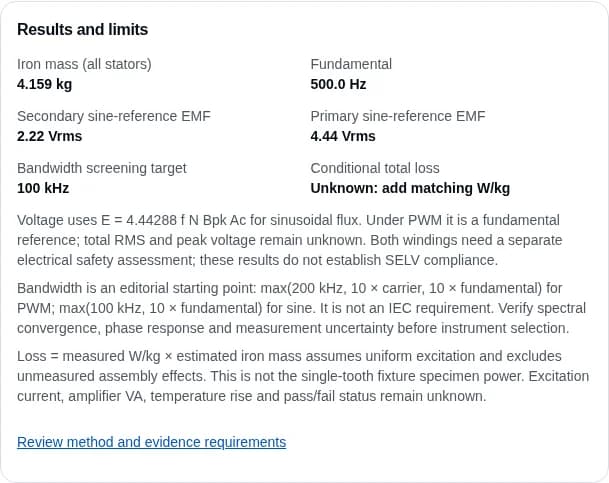
This tool run was captured on 2026-11-07. Start with Reset Defaults, select sinusoidal excitation, set speed to 3,000 rpm (10 pole pairs, 500 Hz), Bpk to 1.0 T, effective section to 100 mm², primary turns to 20 and secondary turns to 10. Leave measured W/kg blank. E2 = 4.44288 × 500 × 10 × 1 × 100e−6 = 2.22 Vrms; E1 = 4.44 Vrms. Loss remains unknown.
Hypothetical Worked Validation Scenarios
Three hypothetical examples show a reproducible voltage calculation, a PWM evidence gap and dual-stator mass accounting. They are not measured customer outcomes.
Hypothetical sine-reference voltage check
Premise: Chosen example inputs: effective section 100 mm², 500 Hz, Bpk 1.0 T, N2 10, N1 20.
Challenge: Separate a reproducible voltage calculation from equipment and safety approval.
Test Protocol: Enter the chosen values in sinusoidal mode. E2 = 4.44288 × 500 × 10 × 1 × 100e−6; E1 uses 20 turns.
Findings: Arithmetic gives E2 = 2.22 Vrms and E1 = 4.44 Vrms. Excitation current, VA, core loss and electrical safety remain unknown.
Hypothetical PWM data gap
Premise: The buyer has a sinusoidal loss map, while the planned motor uses PWM.
Challenge: A carrier setting alone cannot convert that map into validated PWM loss.
Test Protocol: Select PWM and leave W/kg blank; request matching waveform tests at the target B, frequency, temperature and preload.
Findings: The tool reports mass and frequency while loss remains unknown. No assumed harmonic multiplier or delivered efficiency improvement is claimed.
Hypothetical dual-stator mass check
Premise: Two stators have identical OD, ID, thickness, density and iron fraction.
Challenge: Avoid comparing one-stator and two-stator mass bases.
Test Protocol: Change only topology from single-stator to DSSR and restore the same iron volume fraction after the topology default changes.
Findings: The geometric model doubles estimated total iron mass. Conditional loss doubles only if the same measured W/kg genuinely applies to both stators.
Technical FAQ: AFPM Core Performance Testing
Twenty-four answers cover magnetic section definitions, PWM evidence, clamping, temperature-conditioned measurements, phase error and RFQ planning.
Can I use the annular stator face area as the flux section?
Only if it is actually the effective coil-linked section normal to the measured flux. Ring, tooth and back-iron paths differ. Supply a drawing-derived or measured section; the tool leaves voltage unknown if it is blank.
Why are excitation current and amplifier VA unknown?
A grade name and envelope dimensions do not specify nonlinear H(B), gaps, winding impedance, current waveform or fixture losses. Measure or model those inputs with the laboratory before selecting the source.
What does the iron volume fraction mean?
It is occupied iron volume divided by the annular envelope volume, per stator. It is not copper fill. Verify it from the geometry or replace estimated mass with a weighed specimen for acceptance work.
Does a ring test qualify a finished tooth?
It establishes properties of the tested specimen under the stated conditions. A finished tooth can introduce processing stress, gaps and return-yoke corrections. Demonstrate transfer with matched component tests.
Does IEC 60034-2-3:2024 specify a fixed PWM core loss penalty?
The cited publication concerns converter-fed motor loss and efficiency methods. This page has no evidence for a universal material multiplier, so the calculator does not add one.
Can I enter sine W/kg while PWM is selected?
Use only a datum measured at the selected waveform and operating point. If only sine data exists, select sine to examine that baseline or leave PWM loss unknown and request a matching test.
Does the voltage output predict PWM pulse peaks?
No. It is the sinusoidal-flux fundamental reference. PWM total RMS, switching peaks and insulation requirements need recorded waveform and winding data.
Why is specific loss cleared after I change B or frequency?
The previous datum may no longer apply. Changing material, frequency, B, waveform, carrier, topology or fixture clears it so you can enter matching data explicitly.
Is there a universal clamping-pressure limit for SMC?
No limit is established here. Material processing, geometry, contact support and loading direction matter. Agree loads with the assembly engineer and test representative specimens.
Does ISO 3325 measure SMC insulation?
No. ISO 3325:2026 concerns transverse rupture strength of eligible sintered materials. It is not an electrical insulation method; applicability to non-sintered SMC must be established.
Can a loose-tooth resonance predict assembled motor noise?
It can support component comparison, but assembled modes depend on potting, supports, preload and temperature. Validate representative assembly response and operating excitation orders.
How should I compare stressed and unstressed magnetic behavior?
Keep B, frequency, waveform and temperature matched, document contact geometry and preload, and retest after unloading to identify reversible versus permanent changes.
Does calculated core loss give temperature rise?
No. Cooling conditions, thermal paths, heat capacity and local heat sources are missing. Use a separate thermal model and representative assembly test.
Can I use a room-temperature datum at operating temperature?
Only if supporting characterization establishes that transfer. Otherwise request temperature-conditioned measurements and keep the unmeasured condition unknown.
When is transient calorimetry useful?
As an independent loss cross-check when heat capacity, sensor response and parasitic heat flows are characterized. The simple Cth dT/dt approximation is not enough by itself.
Are the scenarios measured customer results?
No. They are explicitly hypothetical planning examples or arithmetic checks. They do not demonstrate a delivered product, certification or customer performance.
Is 10 times carrier bandwidth a standard requirement?
It is an editorial screening heuristic used by this tool. The final choice needs spectrum, phase-response, convergence and uncertainty checks for the actual measurement.
Why can tiny probe delays matter?
At low power factor, relative active-power error is sensitive to voltage-current phase mismatch. The chapter gives a first-order single-frequency arithmetic example; broadband work needs a fuller uncertainty budget.
Is a low voltage result evidence of SELV compliance?
No. Neither the estimated secondary nor primary voltage establishes electrical safety. Pulse peaks, insulation, stored energy, environmental conditions and equipment design require separate assessment.
What if copying is blocked by my browser?
The tool focuses and selects the generated brief. Use Ctrl+C or Cmd+C, or touch and hold to copy. You can also open the prefilled engineering inquiry and review the text there.
Does the tool issue a pass/fail certificate?
No. Buyer and laboratory must agree the applicable method, conditions, limits, uncertainty and decision rule. The output is a planning brief.
Is IEC 60404-6 appropriate for electrical steel?
Its cited public scope excludes electrical steels and soft ferrites. Select an applicable sheet or component procedure with the lab, including the required frequency range.
Does coercivity screening replace AC loss testing?
No. IEC 60404-7 covers coercivity measurement. A production correlation to the desired loss property must be demonstrated and monitored before screening is used for release.
What should an OEM request before placing a test order?
Request method and edition, specimen preparation, operating matrix, sample consumption, fixture corrections, uncertainty, decision rule, named laboratory capability and a separate quote for setup and recurring tests.
Primary Standards: Scope and Applicability
Source scopes checked against public publisher descriptions on 2026-11-07. Full standards may require purchase; verify the applicable edition and procedure with the laboratory. Editorial checklists and arithmetic examples are not standard-mandated limits or measured results.
AC ring-specimen magnetic measurements
Eligible metallic/powder ring specimens, 20 Hz–100 kHz; excludes electrical steels and soft ferrites. The public abstract supports scope, not universal accuracy or fixture conformity.
Loss and efficiency testing of converter-fed AC motors
Complete converter-fed AC motor methods and interpolation; not a prescribed material PWM-loss multiplier or a stand-alone tooth test method.
Open-circuit coercivity measurement
Coercivity measurement; does not establish an eight-second takt time, heat-treatment recipe or universal rejection threshold.
Electrical steel sheet and strip: Epstein frame
Sheet/strip magnetic characterization; published base scope includes AC up to 400 Hz. Agree a different applicable method for higher-frequency component tests.
Surface insulation resistivity of single-strip specimens
Electrical-steel strip/punching surface insulation test under specified conditions. Not a bulk SMC particle-insulation or winding dielectric test. Public method listing; verify contracted edition.
Transverse rupture strength of sintered metal materials
Mechanical strength method for eligible sintered specimens; applicability to a pressed, non-sintered SMC grade must be established. Not an insulation method.
Density of impermeable sintered materials and hardmetals
Density method limited to its material and permeability scope. Do not apply it automatically to porous or resin-bonded SMC; agree a suitable density method.
Ready to Qualify Your Axial Flux Stator Core Performance?
Share your core geometry, operating conditions and required evidence. We can review the request and confirm available testing options, named laboratory capability, scope, cost and delivery before you place an order.
Direct engineering inquiries: [email protected]