
AFPM Core Manufacturing Tolerance
Screen a single air-gap stackup, compare manufacturing evidence, and prepare a drawing review.
By AxialFluxCore · First recorded · Reviewed
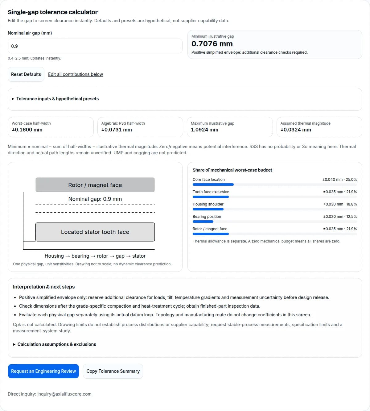
Single-gap tolerance calculator
Edit the gap to screen clearance instantly. Defaults and presets are hypothetical, not supplier capability data.
Worst-case half-width
±0.1600 mm
Algebraic RSS half-width
±0.0731 mm
Maximum illustrative gap
1.0924 mm
Assumed thermal magnitude
±0.0324 mm
Minimum = nominal − sum of half-widths − illustrative thermal magnitude. Zero/negative means potential interference. RSS has no probability or 3σ meaning here. Thermal direction and actual path lengths remain unverified. UMP and cogging are not predicted.
Share of mechanical worst-case budget
Thermal allowance is separate. A zero mechanical budget means all shares are zero.
Interpretation & next steps
- Positive simplified envelope only: reserve additional clearance for loads, tilt, temperature gradients and measurement uncertainty before design release.
- Check dimensions after the grade-specific compaction and heat-treatment cycle; obtain finished-part inspection data.
- Evaluate each physical gap separately using its actual datum loop. Topology and manufacturing route do not change coefficients in this screen.
Cpk is not calculated. Drawing limits do not establish process distributions or supplier capability; request stable-process measurements, specification limits and a measurement-system study.
Calculation assumptions & exclusions
- Single-gap model with five effective symmetric half-width contributions, all sensitivity coefficients equal to 1. Do not enter whole-disc thickness if its sensitivity is 1/2 without converting it.
- Face excursion is a centered +/- allowance relative to the located nominal face. Flatness and TIR are different controls; neither is automatically centered. Resolve location and form from the drawing and avoid double counting.
- RSS is an algebraic comparison of limits only. It is not 3 sigma, a confidence interval or a contact probability. Statistical use requires measured distributions, common coverage and covariance handling.
- Illustrative thermal magnitude: L x (23 - 11) x 10^-6 x (T - 20), with matched path lengths and uniform temperatures. Housing CTE is an assumed 23 x 10^-6/K; 11 x 10^-6/K is a grade-specific core example, not universal.
- The +/- thermal envelope represents unknown direction under those assumptions. Actual signed gap drift requires separate housing/shaft/core path lengths, material properties, temperatures and restraint geometry.
- Dynamic deflection, rotor tilt, centrifugal loads, joint settling and measurement uncertainty are excluded. No UMP, cogging, fatigue, process-capability or design-safety prediction is made.
Direct inquiry: [email protected]
Key decisions before tolerances are released
One loop per gap
Allocate tolerances to the physical gap
Use effective face-position contributions from the actual datum loop. A two-gap assembly needs separate loops; whole-stator thickness does not always have unit sensitivity.
Evidence / scope: ISO 1101:2017 — Geometrical tolerancing
Release margin: not determined
A positive screen is an intermediate result
The tool subtracts specified contributions and an assumed thermal magnitude. It omits load deflection, tilt and joint movement; reserve these before releasing the design.
Engineering review guidance; no measured performance or universal numerical limit asserted.
Capability: supplier confirmation
Compare routes using finished-part evidence
SMC can provide net-shaped components, but its supplier tolerance and Cpk remain unknown here. Compare all routes on the same datum, temperature and inspection state.
Evidence / scope: Höganäs — How to design with Somaloy? · NIST/SEMATECH — What is process capability?
No 3σ claim
RSS of limits has no probability label
The displayed RSS is a mathematical comparison. A statistical prediction requires a defined distribution model and correlations, beyond drawing limits alone.
Evidence / scope: NIST — Combining uncertainty components
0.0324 mm illustrative magnitude
Check thermal direction before compensating
The example uses equal-length housing and core paths. At 45 mm and a 60 K rise, 45 × 12 × 10⁻⁶ × 60 = 0.0324 mm. Actual signed drift depends on the locating scheme.
Evidence / scope: Höganäs — Somaloy 700HR 3P material data at 800 MPa
Method, evidence, limits and sourcing actions
Sources support only their stated scopes. Arithmetic examples and review recommendations are identified separately. Public standards abstracts do not certify this calculator, a drawing or a manufacturing process.
1. Turn the air-gap requirement into a dimensional task
The primary decision is how much clearance remains after the relevant errors and operating movement.
Identify the two active faces defining one gap, the assembly reference temperature and the required operating clearance. The nominal gap alone does not describe disc tilt, tooth-to-tooth height differences or rotor bending.
Gap asymmetry can change magnetic forces, but this page does not calculate force. A universal inverse-square air-gap law is not adequate for a permanent-magnet machine with magnet reluctance, leakage, saturation and load dependence. Use an electromagnetic and structural model for UMP, torque ripple and bearing loads.
Engineering review guidance; no measured performance or universal numerical limit asserted.
2. Build a non-overlapping datum loop
Enter effective single-gap contributions, not unrelated drawing limits.
Trace housing locator → bearing position → rotor/magnet face → air gap → stator active face → housing locator. Check whether each feature has unit, half or another sensitivity to that gap.
The calculator assumes coefficient 1 for each of five symmetric half-widths. For a perfectly centered stator, a total thickness error may contribute half to each gap; an end-located stator can have a different relationship. Convert to effective contributions before entry.
A measured runout envelope may already include face-location and form effects. Do not add the same error again under core height or rotor location. Route and topology selectors provide context and advice; they do not change the equations.
Evidence / scope: ISO 1101:2017 — Geometrical tolerancing
3. Compare SMC, segmented stacks and wound cores
Manufacturing route affects what to inspect; it does not determine a tolerance guarantee.
Höganäs describes dedicated-tool compaction followed by heat treatment for Somaloy components. This supports assessing a net-shape route, not claiming a universal ±0.030 mm tooth height.
For laminated and wound cores, agree the finished condition: bonded or clamped, impregnated or dry, before or after face finishing. Record dimensions in that condition. Whether grinding is needed depends on demonstrated capability and the magnetic surface requirements.
Separate prototype machining or soft tooling from series-production tooling. Ask competing suppliers to quote the same drawing revision, lot size and inspection plan. A generic cost multiplier or route-specific Cpk would obscure the actual tooling, finishing, inspection and reject costs.
Evidence / scope: Höganäs — How to design with Somaloy?
Route comparison: what is known and what remains unknown
Qualitative procurement checks, not supplier capability rankings.
| Route | Evidence to request | Unknown here |
|---|---|---|
| SMC compaction | Finished heat-treated face measurements; grade and tool cavity | Tolerance, Cpk, tool life and quote |
| Segmented lamination | Pack height and face geometry in defined bonding/clamping state | Finishing requirement and reject rate |
| Tape-wound / slotted | Finished active-face geometry after winding, impregnation and slotting | Repeatability, insulation impact and cost |
4. Separate size, form and orientation controls
Flatness and total runout are different characteristics.
Flatness constrains a surface form zone without locating it relative to the motor assembly. Axial runout is evaluated relative to an established rotational datum axis. Face position or profile controls serve another purpose; select them from function and inspection access.
The face-excursion input is an effective centered ± allowance after the nominal face has been located. A raw flatness or TIR zone cannot simply be halved without accounting for location and centering. If only a total zone is known, establish a conservative excursion with the drawing owner.
Use ISO GPS interpretation rules consistently. An envelope requirement is not a substitute for verifying the full assembly loop. The diagrams below are discussion aids, not approved feature-control frames or a declaration of standards compliance.
Evidence / scope: ISO 1101:2017 — Geometrical tolerancing · ISO 8015:2011 — GPS fundamentals · ISO 2768-1:1989 — General linear and angular tolerances
Drawing controls are not interchangeable
Choose controls with the drawing owner under the agreed GPS specification.
| Control / input | What it describes | Required clarification |
|---|---|---|
| Thickness / face location | Size or located face position | Sensitivity to the chosen physical gap |
| Flatness | Surface form zone | Location of that zone relative to nominal |
| Axial runout | Indicated variation about a datum axis | Functional axis and overlap with other terms |
| Effective face excursion input | Centered ± allowance used by this calculator | Derivation from the located face envelope |
5. Reproduce worst-case and algebraic RSS
The tool exposes its arithmetic without attaching unsupported statistical confidence.
Let t₁…t₅ be effective half-widths in mm. Mechanical worst-case half-width W = Σtᵢ; full band = 2W. Algebraic RSS half-width R = √Σtᵢ²; full band = 2R. The thermal magnitude is added separately, not folded into an independent random-error RSS.
For the defaults: W = 0.040 + 0.035 + 0.030 + 0.020 + 0.035 = 0.1600 mm, and R = √0.00535 = 0.0731 mm. With 0.0324 mm assumed thermal magnitude, the illustrative envelope is 0.9000 ± 0.1924 = 0.7076–1.0924 mm.
Interpreting RSS statistically requires more information than these limits. Correlated contributions, nonzero means and different coverage factors must be handled explicitly. A positive RSS lower value cannot override a nonpositive worst-case value.
Evidence / scope: NIST — Combining uncertainty components
Method selection and release limits
Mechanical limits are distinct from statistical process data.
| Method | Required inputs | Decision boundary |
|---|---|---|
| Worst-case sum | Effective bounds and sensitivities | Only includes the contributors modeled |
| Algebraic RSS in this tool | Same half-widths as worst case | Comparison only; no coverage probability |
| Statistical simulation | Distributions, correlations, means and sensitivities | Validate against measured assemblies |
| Running-clearance review | Thermal, structural and dynamic movement plus uncertainty | Required before release |
6. Treat thermal growth as a path-dependent shift
A magnitude example helps reveal sensitivity; it does not fix the sign of a hot gap.
The tool uses Δ = L × (23 − 11) × 10⁻⁶ × (T − 20) mm. The housing coefficient 23 × 10⁻⁶/K is an illustrative assumption. The core coefficient 11 × 10⁻⁶/K has a grade-specific Somaloy 700HR 3P reference and must not be generalized to every core.
Equal path lengths and uniform temperatures are assumed. The displayed interval nominal ± (W + Δ) explores both thermal directions under those assumptions. It is not a bound on arbitrary unequal paths or temperature gradients.
For a release calculation, obtain housing, shaft, bearing and core lengths, actual material data, local temperatures and restraints. Determine signed face movement from a common reference before choosing shims or cold offsets.
Evidence / scope: Höganäs — Somaloy 700HR 3P material data at 800 MPa
Thermal scenario and its limits
Assumed values for the tool; not a general materials database.
| Term | Tool value | Evidence / limit |
|---|---|---|
| Housing CTE | 23 × 10⁻⁶/K | Illustrative assumption; confirm alloy and temperature |
| Core CTE | 11 × 10⁻⁶/K | Somaloy 700HR 3P example only |
| Path lengths | Equal, default 45 mm | Confirm actual housing, shaft and core paths |
| Temperature rise | Default 60 K from 20°C | Uniform assumed temperature; no gradients |
| Gap drift sign | Unknown; ± magnitude explored | Requires locating and restraint geometry |
7. Make inspection state reproducible
A useful tolerance report defines the fixture, temperature, datum construction and measurement uncertainty.
Specify which tooth surfaces are sampled and whether the core is free, clamped or assembled. Keep location, flatness, coplanarity and runout results separate so their overlap can be reviewed.
A CMM can sample face geometry; a rotary fixture can evaluate runout about the functional axis. Neither method has a universal uncertainty or cycle time. Ask for the uncertainty budget and fixture repeatability relative to the actual tolerance.
Evidence / scope: ISO 1101:2017 — Geometrical tolerancing
Inspection handoff
Specify the measurement condition before comparing supplier reports.
| Characteristic | Possible method | Record with result |
|---|---|---|
| Located tooth face | CMM / fixture height measurement | Datum fit, fixture load, temperature and uncertainty |
| Axial runout | Rotary fixture and indicator / scanning | Axis realization, measurement radius and point coverage |
| Assembly gap | Accessible gap measurement / validated fixture | Local minima, assembly state and gauge suitability |
| Process capability | Stable-process measurement study | Limits, mean, spread, sampling coverage and uncertainty |
8. Relax the contributor that actually drives cost
Use the budget bars to select a negotiation topic, then check process evidence.
Large contributors deserve investigation, but the largest tolerance is not always the cheapest to reduce. Ask whether a common datum fixture, changed locating shoulder or selective shim removes assembly variation more economically than tighter core tooling.
Compare nonrecurring tooling, finishing, inspection, scrap exposure and traceability effort separately. Selective assembly adds binning and service-part constraints; a wider nominal gap needs electromagnetic revalidation.
Engineering review guidance; no measured performance or universal numerical limit asserted.
Cost, misuse and scenario risks
Engineering review guidance; no generic cost or performance multipliers.
| Risk | Tradeoff | Mitigation / alternative |
|---|---|---|
| Using the positive screen as release approval | Omitted operating movement can consume clearance | Add thermal/structural validation and measured uncertainty |
| Tightening every core dimension | Tooling, finishing, inspection and reject costs | Investigate common-datum fixtures or selective shimming |
| Using RSS with correlated or biased processes | Apparent margin may be overstated | Retain worst-case screen; model distributions explicitly |
| Using one loop for both gaps | Centering and end-location sensitivities differ | Calculate each gap from the actual locating scheme |
9. Reserve for bolted-joint movement
The calculator excludes settling and preload changes.
Surface embedding, thermal cycles and contact pressure can change joint clamp conditions. No fixed micrometre settlement or percentage preload loss is asserted here.
For the actual joint, evaluate the fastener and clamped-member stiffness, surface condition and temperature history. Measure face position after representative assembly and thermal cycling; include the resulting movement in the detailed clearance budget.
Engineering review guidance; no measured performance or universal numerical limit asserted.
10. Verify running deflection and tilt separately
A balanced rotor can still deflect or tilt under operating loads.
ISO 21940-11 concerns balancing rotors with rigid behaviour. A balance grade does not determine allowable air-gap deflection, disc stiffness or bearing compliance.
Evaluate speed-dependent disc deformation, magnetic attraction, shock loads and bearing support. Measure or simulate the minimum local running gap around the full annulus; static face runout alone is incomplete.
Evidence / scope: ISO 21940-11:2016 — Balancing rigid rotors
11. Verify SMC after its actual thermal cycle
Grade and process condition matter more than a generic powder label.
The cited 700HR 3P sheet lists 800 MPa compaction, an 80°C die and a 530°C steam heat treatment. These conditions identify that material data set; they are not universal process instructions.
Request part-level dimensions after heat treatment and any subsequent handling or machining. Tool wear, filling and local density can be investigated through measured trends rather than assumed stroke-count maintenance limits.
Evidence / scope: Höganäs — How to design with Somaloy? · Höganäs — Somaloy 700HR 3P material data at 800 MPa
12. Validate finishing and insulation together
A geometrically flatter face must still meet its magnetic and mechanical requirements.
Agree the bonding, clamping, winding and machining sequence before measuring a laminated or wound core. Face finishing may affect burrs, edge insulation and bonding; evaluate those effects on representative parts.
Do not prescribe generic acid etching, mandatory grinding or adhesive cure pressure from this guide. Obtain the material supplier and process owner’s approved instructions, then verify dimensional and magnetic acceptance together.
Engineering review guidance; no measured performance or universal numerical limit asserted.
13. Ask for capability evidence, not a route label
Cpk cannot be inferred from a tolerance input or a preset.
NIST defines Cpk using the nearest specification limit, process mean and three standard deviations. It is a property of a measured characteristic under a stated process condition.
Agree a sampling plan spanning relevant cavities, shifts and tool age, verify measurement adequacy and report uncertainty. A first-article dimensional report serves a different purpose from a capability study. Acceptance thresholds belong in the customer agreement.
Evidence / scope: NIST/SEMATECH — What is process capability?
14. Prepare the next engineering review
Carry the inputs, assumptions and missing evidence into one review package.
Copy the summary and send the drawing revision, datum loop, selected physical gap, finished-part condition, operating temperatures, speed/load cases, annual quantity and required inspection records.
Ask the supplier to identify confirmed dimensions, assumptions needing approval, proposed tooling or finishing, and the trial needed to establish capability. Keep unverified thermal and dynamic terms open until the motor and process owners resolve them.
Engineering review guidance; no measured performance or universal numerical limit asserted.
Default calculation audit trail
All values are hypothetical inputs or reproducible arithmetic; units mm.
| Quantity | Calculation | Value |
|---|---|---|
| Mechanical half-width W | 0.040 + 0.035 + 0.030 + 0.020 + 0.035 | 0.1600 |
| RSS half-width R | sqrt(0.040² + 0.035² + 0.030² + 0.020² + 0.035²) | 0.0731 |
| Thermal magnitude Δ | 45 × 12 × 10⁻⁶ × (80 − 20) | 0.0324 |
| Minimum / maximum illustrative gap | 0.9000 ± (0.1600 + 0.0324) | 0.7076 / 1.0924 |
Four reproducible hypothetical scenarios
These use the same presets and model as the calculator. No customer results, measured yield or certification is claimed. Load the matching preset above to inspect every input.
EV Traction Dual-Rotor (High Precision SMC)
High-torque automotive direct drive with die-compacted SMC core, preloaded angular contact bearings, and ground rotor carriers.
- Assumptions:
- 0.85 mm nominal; 50 mm matched thermal length; 110°C uniform temperature.
- Process:
- sum effective half-widths = 0.1350 mm; subtract thermal magnitude 0.0540 mm separately.
- Illustrative result:
- 0.6610–1.0390 mm.
Positive simplified envelope only: reserve additional clearance for loads, tilt, temperature gradients and measurement uncertainty before design release.
Aviation Drone Yokeless Module (SMC Teeth)
Ultra-lightweight segmented tooth carrier with carbon-fiber structure requiring tight individual tooth height tolerance.
- Assumptions:
- 0.7 mm nominal; 35 mm matched thermal length; 85°C uniform temperature.
- Process:
- sum effective half-widths = 0.1200 mm; subtract thermal magnitude 0.0273 mm separately.
- Illustrative result:
- 0.5527–0.8473 mm.
Positive simplified envelope only: reserve additional clearance for loads, tilt, temperature gradients and measurement uncertainty before design release.
Industrial Pump (Segmented Lamination)
Cost-sensitive continuous duty pump using bonded silicon steel segmented laminations with standard commercial tolerances.
- Assumptions:
- 1.1 mm nominal; 55 mm matched thermal length; 75°C uniform temperature.
- Process:
- sum effective half-widths = 0.2800 mm; subtract thermal magnitude 0.0363 mm separately.
- Illustrative result:
- 0.7837–1.4163 mm.
Positive simplified envelope only: reserve additional clearance for loads, tilt, temperature gradients and measurement uncertainty before design release.
Robotic Servo Joint (Tape-Wound Slotted)
Compact hollow-shaft robotic joint requiring minimal cogging torque and sub-millimeter air gap retention.
- Assumptions:
- 0.75 mm nominal; 30 mm matched thermal length; 65°C uniform temperature.
- Process:
- sum effective half-widths = 0.1650 mm; subtract thermal magnitude 0.0162 mm separately.
- Illustrative result:
- 0.5688–0.9312 mm.
Positive simplified envelope only: reserve additional clearance for loads, tilt, temperature gradients and measurement uncertainty before design release.
Technical FAQs by decision type
Tool & model
What does the minimum gap result mean?
It is the nominal gap minus five effective half-widths and the illustrative thermal magnitude. Zero or a negative value indicates potential contact. A positive value still excludes load deflection, tilt, settling and measurement uncertainty.
Tool & model
Why does selecting a topology not change the numbers?
Topology is context only. The calculator uses coefficient 1 for effective inputs in one physical gap. Convert the actual drawing sensitivities first and assess each gap separately.
Tool & model
Can I enter a raw flatness or TIR value?
Not without interpreting its location and centering. The face-excursion field requires a centered one-sided allowance. Flatness and runout are different controls, and an existing face envelope may already include other contributions.
Tool & model
Is the RSS result a 3σ clearance prediction?
No. It is the square root of the sum of squared input half-widths. This page has no measured distributions or covariance model and assigns no probability to RSS.
Tool & model
What happens if all mechanical contributions are zero?
The mechanical worst-case and RSS bands become zero and budget shares are zero. The separate illustrative thermal magnitude still applies unless the temperature is at the 20°C reference.
Tool & model
How are missing or invalid inputs handled?
The tool hides the calculation, identifies the invalid fields and offers reset or a drawing-review path. Values outside the displayed ranges are not extrapolated.
Thermal & operation
Does the aluminum housing always close the gap when hot?
No. The direction depends on the actual locating and restraint scheme. The tool explores both signs of a magnitude based on equal path lengths and uniform temperature, not a signed prediction.
Thermal & operation
Does this tool calculate UMP or cogging torque?
No. Those outputs require magnetic geometry, material behaviour, excitation and structural information absent from this model. Use an appropriate electromagnetic and mechanical analysis.
Thermal & operation
Does a balance grade guarantee running clearance?
No. Rotor balancing and running deflection are separate checks. Evaluate rotor stiffness, magnetic loads, support compliance and speed-dependent deformation.
Manufacturing & sourcing
What tolerance can my SMC supplier guarantee?
That remains unconfirmed here. Obtain finished-part data for the actual geometry, grade, cavity and heat-treatment condition, then agree the drawing limits and inspection plan.
Manufacturing & sourcing
Do all laminated stacks require face grinding?
No universal requirement is asserted. Measure the finished pack in its specified condition. If finishing is proposed, validate dimensional improvement and insulation or magnetic effects together.
Manufacturing & sourcing
Can the preset results be used as customer case studies?
No. All presets and scenarios are hypothetical arithmetic examples. They are not measured motors, supplier acceptance records or proof of application qualification.
Manufacturing & sourcing
How can selective assembly reduce tolerance costs?
Measured part bins and matched shims can reduce assembled variation, but require traceability, controlled assembly and a service-part strategy. Compare this cost with tighter component limits and an altered locating scheme.
Inspection & quality
What Cpk value is required?
The customer agreement must define the required capability and study plan. This page neither assigns a Cpk to a manufacturing route nor claims a universal automotive threshold.
Inspection & quality
Is a first-article report a capability study?
A dimensional first-article report confirms the inspected samples against the drawing. Process capability needs a representative measurement study under a stated process and sampling plan.
Inspection & quality
What should I send for the next review?
Send the drawing revision, datum loop, single gap being evaluated, copied inputs and assumptions, finished-part condition, temperatures, speed/load cases, volume and required inspection records. Identify unknown thermal and dynamic terms explicitly.
Primary sources, scope and unresolved evidence
Source identity and public scope checked 2026-11-02. Full standards may require purchase; confirm contractual editions. Supplier tolerances, capability, tool life, cost, dynamic clearance and case-study outcomes are unverified and are not presented as data.
AxialFluxCore maintains this guide with an annual editorial review, or earlier when a cited source or the calculation method changes. Rebuilding the site does not change its review date.
ISO 1101:2017 — Geometrical tolerancing
Public scope covers symbols and interpretation of form, orientation, location and run-out controls. It does not establish AFPM capability limits.
Open primary source ↗ISO 8015:2011 — GPS fundamentals
Public scope identifies fundamental GPS interpretation rules. Apply the purchased standard and the drawing specification for detailed requirements.
Open primary source ↗ISO 2768-1:1989 — General linear and angular tolerances
General tolerance classes for applicable dimensions without individual indications. Not an AFPM air-gap design standard; confirm the contract edition.
Open primary source ↗ISO 21940-11:2016 — Balancing rigid rotors
Residual unbalance, correction planes and balancing errors for rigid rotors. Does not establish allowable disc deflection or guarantee a running air gap.
Open primary source ↗Höganäs — How to design with Somaloy?
Manufacturer overview of dedicated-tool compaction, net-shape potential and subsequent heat treatment. Does not publish a universal tooth tolerance or Cpk.
Open primary source ↗Höganäs — Somaloy 700HR 3P material data at 800 MPa
Grade-specific example: thermal expansion 11 × 10⁻⁶/K, die temperature 80°C and heat treatment at 530°C in steam. Not a recipe for other grades.
Open primary source ↗NIST/SEMATECH — What is process capability?
Capability compares specification limits with measured process spread and centering. Sample size, distribution and estimate uncertainty matter; route names do not supply Cpk.
Open primary source ↗NIST — Combining uncertainty components
Combines standard uncertainties with covariance where appropriate. Drawing tolerance limits are not automatically standard deviations.
Open primary source ↗Related core and manufacturing capabilities
Ready to Validate Your AFPM Core Manufacturing Tolerance?
Send the drawing revision, datum scheme and copied assumptions. Ask for feasibility, missing evidence, proposed trial inspection and a quote scope.
Request an Engineering Review