
1. Five decisions before releasing a core design
1.Start with the flux circuit. A yokeless stator still needs mechanical retention and rotor return paths. Topology alone does not certify mass savings. [S8]
2.Treat material and process as one specification. Match grade suffix, compaction, heat treatment and specimen before using loss data. [S2]
3.Use the right test family. Electrical steel and powder-composite tests have different scopes; request the applicable procedure. [S3] [S4] [S5]
4.Separate known geometry from unknown performance. The equations below reproduce the tool; saturation, loss and torque remain open engineering questions. Method and assumptions.
5.Resolve tooling and assembly constraints before freezing the magnetic envelope. A net-shape route needs a drawing-specific manufacturing review. [S6]
2. Topology sets the return path
Use the actual flux loop to decide what must be sized. “NN” and “NS” here describe facing rotor-pole arrangements; confirm the convention against the rotor drawing. The diagrams are idealized circuits, not winding or structural layouts. Yokeless construction is discussed in the institutional chapter [S8]; the original paper is indexed in [S1].
| Circuit | Stator return-yoke estimate | What remains unknown |
|---|---|---|
| YASA / yokeless | N/A — axial through-flux | Segment retention, rotor yokes, end leakage and local tooth loading |
| TORUS-NS | N/A — axial through-flux | Any support web thickness is a mechanical decision, not a fixed 2 mm |
| TORUS-NN | Φ / (2 × By × k × radial span) | Branch symmetry, local corners, winding layout and peak-load saturation |
| Single rotor / single stator | Same equal-branch screening equation | Actual return path, axial attraction, bearing and rotor-disc deflection |
Two rotor discs can oppose nominal axial forces, but tolerances and deflection can create unequal gaps. A symmetric drawing is not evidence that forces cancel under every operating condition.
3. Reproduce the sizing calculation
These are direct geometry and flux-continuity calculations under stated assumptions, rather than an empirical motor-performance model. Do and Di refer to the active core face, not a housing diameter. Bg is spatially averaged over the active pole face at peak alignment. No fitted leakage correction is applied.
| Step | Equation | Boundary / interpretation |
|---|---|---|
| Radial active span | L = (Do − Di) / 2 | Requires Do > Di; no winding clearance or cooling allowance |
| Active area per pole | Ap = π(Do² − Di²) × αp / (4 × 2p) | Uniform annulus and pole-arc fraction; no skew or edge correction |
| Electrical frequency | f = p × n / 60 [Hz] | p is pole pairs; n is mechanical rpm; inverter carrier frequency is separate |
| Pole flux | Φ = Bg × Ap × 10⁻⁶ | Pole-face spatial average at peak alignment, not a local maximum |
| Aggregate gross tooth area / pole | At = Φ × 10⁶ / (Bt × k) | Equivalent tooth group; does not determine individual teeth or slot fill |
| Return-yoke depth | hy = Φ × 10⁶ / (2 × By × k × L) | Two equal circumferential return branches; N/A for through-flux |
k defaults to 1. Use a measured steel stack factor if Bt/By refer to steel material flux density. Do not apply an extra lamination-style reduction to bulk SMC data. More tooth area follows from a lower Bt target or lower k; neither proves thermal or mechanical feasibility.
The model has no slot count or current waveform. Its area per pole cannot be used as a physical tooth drawing or multiplied by a guessed tooth count to obtain a production mass. Coupled magnetic and winding design must allocate that flux among actual segments.
4. What material data can actually tell you
The table shows published typical SMC ring values under one stated compaction condition. B at H = 10 kA/m is a magnetization point, not a saturation ceiling. Conditions: 800 MPa, 1 T loss excitation, 5 × 5 mm cross-section; see the source for heat-treatment routes. [S2]
| Exact grade | B at 10 kA/m [T] | 400 Hz loss [W/kg] | 1,000 Hz loss [W/kg] |
|---|---|---|---|
| Somaloy 700HR 5P | 1.57 | 30 | 92 |
| Somaloy 700 3P | 1.61 | 45 | 132 |
| Somaloy 1000 5P | 1.59 | 31 | 103 |
Ring and sheet measurements are not directly interchangeable [S2]. The following comparison is our engineering review framework, not a ranking of measured motor efficiency:
| Candidate | Decision to investigate | Required comparison evidence |
|---|---|---|
| SMC component | 3D shape and flux routing versus tooling and process constraints | Exact powder suffix, density/heat treatment, component geometry, B-H and loss maps |
| 0.20 / 0.35 mm electrical steel | Stack orientation, cutting route and local transverse fields | Exact sheet grade, finished stack factor, edge condition, loss at matched B/f/temperature |
| Amorphous ribbon | Assembly, cutting and bonding compatibility | Exact alloy, annealed component measurements and supplier mechanical limits |
For context, the Metglas brochure lists typical 2605SA1 saturation induction of 1.56 T and density 7.18 g/cm³; it also says these values are not guaranteed [S7]. That transformer-material reference supplies neither a 1K101 equivalence nor a 400 Hz motor-loss guarantee. Such performance is marked unverified in the tool.
5. Diameter ratio is a trade-off, not a universal optimum
Di/Do describes the annular envelope. The best value changes with the quantity held fixed: outer diameter, current loading, conductor space, cooling surface or allowable mechanical stress. This tool does not impose a “safe” ratio band or predict torque from a single diameter-ratio expression.
For example, direct integration of uniform tangential shear stress τ over one annular face gives T = 2πτ(Ro³ − Ri³)/3. At fixed Ro and τ this scales with (1 − λ³), where λ = Ri/Ro. A different model that assumes a loading term proportional to λ can instead contain λ(1 − λ²), whose mathematical maximum is 1/√3. Those are different assumptions, so 0.577 cannot be applied as a general design rule.
| Change at fixed Do | Geometric effect | Next check |
|---|---|---|
| Decrease Di | More radial active span; smaller pitch at the inner radius | Coil insertion, tooth-root flux and inner-end-turn cooling |
| Increase Di | Less radial active span; more central clearance | Available torque at the actual loading and thermal limits |
| Increase pole pairs | Smaller area per pole and higher electrical frequency at fixed speed | Winding feasibility, local harmonics and measured loss |
6. Three worked, hypothetical sizing scenarios
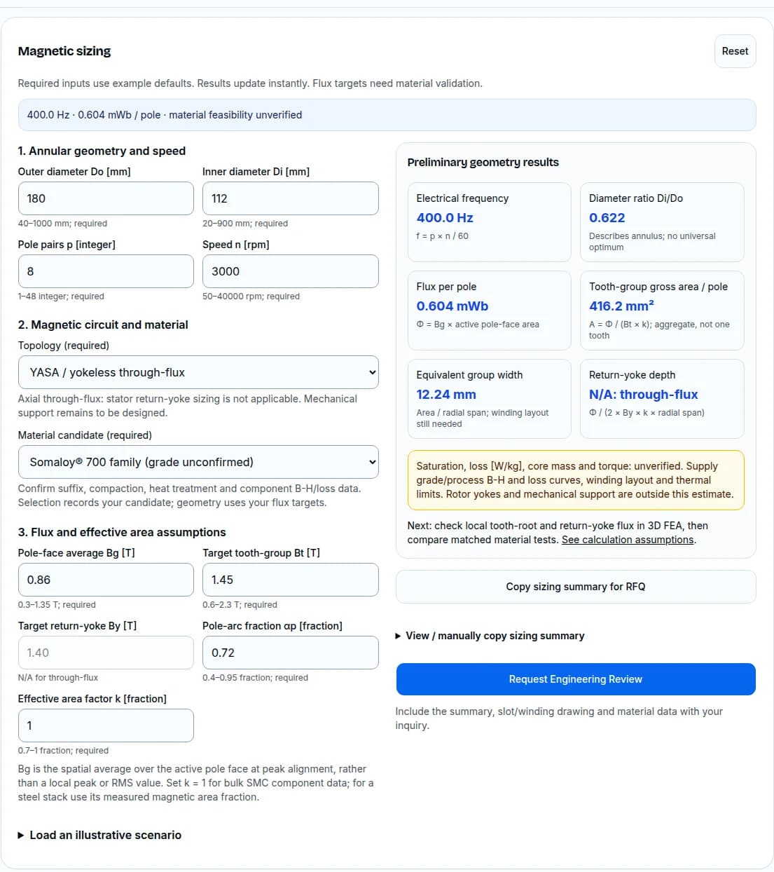
These reproduce the calculator presets, not production motor specifications. All use the displayed geometry equations without a leakage correction; tooth targets and k are assumptions. Load a scenario from the tool to inspect or change it.
| Example / input basis | Operating point | Calculated outputs | Decision / limitation |
|---|---|---|---|
| Through-flux example Do/Di: 180/112 mm; p=8; αp=0.72; Bg/Bt/By=0.86/1.45/N/A T; k=1 | 3000 rpm → 400 Hz | 0.604 mWb/pole; 416.2 mm²/group; yoke N/A | Through-flux example: allocate area to actual segments and check support. |
| 1,000 Hz example Do/Di: 145/92 mm; p=10; αp=0.70; Bg/Bt/By=0.82/1.55/N/A T; k=0.95 | 6000 rpm → 1000 Hz | 0.283 mWb/pole; 192.3 mm²/group; yoke N/A | At 1,000 Hz, request matched material-loss evidence; no automatic SMC/steel ranking. |
| Return-yoke example Do/Di: 260/160 mm; p=4; αp=0.75; Bg/Bt/By=0.80/1.65/1.45 T; k=0.95 | 1500 rpm → 100 Hz | 2.474 mWb/pole; 1578.3 mm²/group; yoke 17.96 mm | Equal-branch yoke estimate: verify local return-path flux before a drawing release. |
A numerical area that fits the annulus can still fail the winding, cooling or peak-current design. Use these results to frame simulation and supplier questions rather than accepting a feasible-looking number as release evidence.
7. Air gap, leakage and magnet margin need a full circuit
The calculator accepts Bg as an input; it does not solve magnet thickness. A simple screening relation Rgap = geff/(μ0 A) is only one reluctance term. Slotting, coatings, magnet recoil, nonlinear core reluctance and fringing must be modeled consistently for the actual topology. There is no universal magnet-volume uplift for SMC in this guide.
Use temperature-dependent magnet demagnetization curves with your current limits, fault trajectory and field-weakening strategy. A grade name or one “safe Pc” cannot certify margin. If those curves are missing, the minimum next step is to obtain the supplier curve set before choosing magnet thickness.
8. A loss budget needs waveform and temperature evidence
Frequency alone does not establish core loss. Local flux amplitude, waveform, vector rotation, material processing and temperature all affect the evidence needed. PWM ripple introduces excitation that a single sinusoidal operating point does not describe. We do not apply a fixed PWM penalty or publish invented Bertotti coefficients.
For a preliminary thermal budget, obtain a calibrated loss map at representative B, f and temperature, then integrate loss density over a validated field and mass distribution. Check tooth tips, return corners and conducting supports separately. Until that information exists, the calculator reports loss and mass as unverified instead of returning an apparently precise W/kg value.
9. Risk, cost and scenario mismatch review
This is an engineering triage list, not a completed safety analysis or qualification plan. Risk ratings and drawing limits require your loads, materials and acceptance criteria.
| Risk / trigger | Decision impact | Minimum mitigation / alternative |
|---|---|---|
| Misuse: pole-group result treated as one tooth | Wrong local flux, winding space or mass estimate | Map actual slots, coil distribution and pole overlap; use local 3D field checks |
| Local tooth-root or return-yoke concentration | Operating point may exceed the accepted loss/MMF budget | Check nonlinear B-H at operating temperature; widen the constrained section or reduce target loading |
| Unequal air gaps under load | Axial force and rotor/support deflection | Evaluate tolerance stack, bearings and deflection together; adjust support layout |
| Hot magnets during faults / field weakening | Irreversible loss of magnetic performance | Use supplier hot curves and transient current trajectories; revise grade or circuit if needed |
| Cost: dedicated SMC die before geometry stabilizes | Tooling rework and supplier qualification delay | Agree a prototype route and drawing freeze criteria before a production tool order |
| Scenario mismatch: sheet coupon used as motor loss | Underestimated thermal burden and cooling cost | Request representative processed components; calibrate against motorette or prototype tests |
| Process change: coating damage, burrs or density variation | Loss, assembly or mechanical deviation | Agree insulation, density and dimensional checks with the selected process owner |
For low volumes, compare the full cost of prototype fabrication, assembly, test and iteration before committing to a dedicated pressing route. For repeat production, obtain quotes at the same drawing revision, material condition, inspection scope and annual quantity. No universal cost winner is implied.
10. Validate the material, then the assembled magnetic circuit
| Evidence | Published scope / purpose | What it cannot establish alone |
|---|---|---|
| Powder / soft-metal ring tests [S3] | IEC 60404-6: 20 Hz–100 kHz for covered materials, excluding electrical steels and soft ferrites | Finished motor losses, local hot spots or torque |
| Electrical steel sheet / strip [S4] | IEC 60404-2: AC up to 400 Hz and DC, Epstein frame | High-frequency processed AFPM tooth behavior |
| Medium-frequency electrical steel [S5] | IEC 60404-10: 400–10,000 Hz, Epstein frame | Inverter-specific or assembled-machine validation |
| Representative core / motorette / motor | Project test: correlate local flux, loss and temperatures with simulation | Performance outside the tested and validated envelope |
Proceed from supplier material evidence to processed-component measurements, then correlate with the assembled circuit. Record test temperature, waveform, geometry, measurement uncertainty and acceptance criteria. Standards define methods within their scope; a reference number is not proof that a supplied core meets your target.
11. Make the next engineering review actionable
Copy the calculator summary and add what it cannot infer: pole/slot winding layout, local flux targets at load, magnet and mechanical air-gap stack, speed/current duty cycle, temperature limits, cooling arrangement, drawing revision and quantity. Mark unknowns explicitly so the review can define the next measurement or model rather than guessing.
For SMC, ask the supplier to set compaction, heat-treatment, ejection, density and inspection requirements against the actual drawing [S6]. Universal draft, wall-thickness and fillet values are not imposed here. For laminations, agree how cutting, insulation and assembly will be assessed after processing.
Need a manufacturability review?
Send known dimensions and duty targets. If a material curve or slot layout is missing, identify it in the inquiry so the next step is clear.
Request Engineering Review12. Sources, review date and evidence limits
Sources checked 2026-10-22. Links below distinguish manufacturer typical data, institutional research and public standard scopes. Geometry equations and review recommendations are our stated analytical reasoning. Published commercial-motor internal dimensions, fixed SMC/steel crossover frequencies and universal magnet safety thresholds are not supported here.
- [S1] Woolmer & McCulloch — Analysis of the Yokeless and Segmented Armature Machine
2007 · IEEE IEMDC · DOI 10.1109/IEMDC.2007.382753 · accessed 2026-10-22
Oxford bibliographic record. Confirms authorship and publication; no numerical performance claims are inferred from the record.
- [S2] Höganäs — Somaloy 3P Material Data
2025 · 2273HOG-3 · pp. 2, 4–5 · accessed 2026-10-22
Typical process-specific ring data and comparison conditions; B at a stated H is not a saturation limit. Does not predict finished-motor loss.
- [S3] IEC 60404-6:2018 — Ring specimen measurements
2018 · amendment 2021 listed by IEC · accessed 2026-10-22
Public scope: AC tests from 20 Hz to 100 kHz for specified soft metallic and powder materials; excludes electrical steels and soft ferrites. Full paid clauses were not reviewed.
- [S4] IEC 60404-2:1996 — Electrical steel Epstein measurements
1996 · amendment 2008 listed by IEC · accessed 2026-10-22
Public scope: electrical steel sheet/strip AC measurements up to 400 Hz and DC measurements. Does not validate a finished AFPM tooth.
- [S5] IEC 60404-10:2016 — Electrical steel at medium frequencies
2016 · corrigendum 2018 · accessed 2026-10-22
Public scope: electrical steel sheet/strip at 400–10,000 Hz using an Epstein frame. Qualification needs the complete agreed test procedure.
- [S6] Höganäs — How to design with Somaloy?
2025 · 1558HOG-4 · pp. 1–2 · accessed 2026-10-22
Compaction, heat treatment and manufacturing considerations. Supplier DFM review must set drawing-specific tolerances and tooling requirements.
- [S7] Metglas — Power brochure
Manufacturer brochure · file hosted under 2016/12 · accessed 2026-10-22
Transformer-material context: typical 2605SA1 saturation induction 1.56 T and density 7.18 g/cm³, explicitly not guaranteed. Not a 400 Hz AFPM motor-loss benchmark.
- [S8] Ahmed Hemeida — Electromagnetic and thermal design of axial flux permanent magnet synchronous machines
2017 · Ghent University PhD thesis · YASA topology discussion · accessed 2026-10-22
Yokeless segmented construction and its magnetic/mechanical implications; does not establish a universal motor mass saving.